Hi Borys,
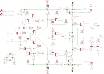
some more precision needed : on schematic are quite difficult to read (R3=2k2? and R19=560r?) R18 trimer is value lefting.
Marc
some more precision needed : on schematic are quite difficult to read (R3=2k2? and R19=560r?) R18 trimer is value lefting.
Marc
R3=2k2
R5=560R
trimer for bias 1k
Thanks. I will check a last time routing job. If i have enough time tomorrow i will etch a pair board.
Marc
Hi Borys,
could you detail you first power and bias level adjustment steps? I've order 2 sanken 2sc2922/2Sa1216 and have on stock MJL3281/1302, MJL4281/4302, as MJW3281/1302 for testing.
Marc
Marc
could you detail you first power and bias level adjustment steps? I've order 2 sanken 2sc2922/2Sa1216 and have on stock MJL3281/1302, MJL4281/4302, as MJW3281/1302 for testing.
Marc
Marc
1. Set 1k trimer at max value, set offset trimmer to get 330R all together with 680R resistor (they are parallel)
2. Power up the amp with +/-35V (or similar voltage), you can use 10R-22R/5W resistors in rails for first run and setup
3. Set up offset at first close to zero.
4. Set up bias trimmer to get around 22mV across 0,22R emiter resistors = 100mA
5. Check and correct offset trimmer again.
Offset may drifft a bit when cold/hot, so for example:
If offset is rising when heating up, set it cold aprox -5 -10mV and when heating up it will go to 0 or +5mV.
Hi,
I have enough room on my board to place 18mm diam elco near output BJT. Do you see an advantage to swap from 1000uF to 2200uf?
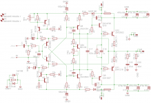
I rearrage the board by turning VAS transistor the other side so that pad are facing the middle line. I could reduce starps number for 5 to for 4.
Marc
I have enough room on my board to place 18mm diam elco near output BJT. Do you see an advantage to swap from 1000uF to 2200uf?
I rearrage the board by turning VAS transistor the other side so that pad are facing the middle line. I could reduce starps number for 5 to for 4.
Marc
Attachments

Last edited:
Hi,
I have enough room on my board to place 18mm diam elco near output BJT. Do you see an advantage to swap from 1000uF to 2200uf?
I rearrage the board by turning VAS transistor the other side so that pad are facing the middle line. I could reduce starps number for 5 to for 4.
Marc
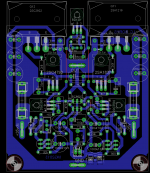
Very nice layout !!!
The cap near o/p transistor is very good to have it.
1mF vs 2,2mF - I do not know If there would be audiable difference but I have done some tests with 1mF and is doing the job fine (panasonic fc 1000uf/10V in my case)
Very nice layout !!!
The cap near o/p transistor is very good to have it.
1mF vs 2,2mF - I do not know If there would be audiable difference but I have done some tests with 1mF and is doing the job fine (panasonic fc 1000uf/10V in my case)
I was not speaking from those in input section but those how are on power supply rail near ouput BJT. In your schematic you put 2x470uf that replace by a 1000µf due location and place available.
Marc
I was not speaking from those in input section but those how are on power supply rail near ouput BJT. In your schematic you put 2x470uf that replace by a 1000µf due location and place available.
Marc
Better is to put two small caps (lower impedance) than one bigger but in this case it prapobly will not make a huge diffrence. The caps are after fuse - so pulse response and impedance are more important tha amaunt of capacity.
Better is to put two small caps (lower impedance) than one bigger but in this case it prapobly will not make a huge diffrence. The caps are after fuse - so pulse response and impedance are more important tha amaunt of capacity.
OK for these reason 2x470µF could theoricaly be better as 1x1000µF
Marc
Here is latest layout evolution : I reswap from 1000uf 50v to 470uf 50v (3u beacause i had room) and some others minor cosmetic correction as parts allignement. I rename all parts to have logical name succesion.
Marc
Marc
Attachments
Good job. After you finish can You post the thermo transfer file too, I will maybe try sanken version too - looks nice and tasty.
Good job. After you finish can You post the thermo transfer file too, I will maybe try sanken version too - looks nice and tasty.
With pleasure...
Marc
Today I had few spare minutes and plugged in latfet version of the amp. The only difference at the first is the bass, I do not know why but I feel stright away that is not that powerfull as with bjt and irfp. The best and strongest bas kick is with bjt wersion, but irfp version looks like has deeper bass anyway.
When I will have more time I will do A and B test for comparasion (but the bass is audiable stright away).
When I will have more time I will do A and B test for comparasion (but the bass is audiable stright away).
I begin DIY amp with latfet schema, than quasi with mosfet an last quasi with BJT and it's the one i prefer.
Marc
Marc
Today I had few spare minutes and plugged in latfet version of the amp. The only difference at the first is the bass, I do not know why but I feel stright away that is not that powerfull as with bjt and irfp. The best and strongest bas kick is with bjt wersion, but irfp version looks like has deeper bass anyway.
When I will have more time I will do A and B test for comparasion (but the bass is audiable stright away).
You right about that.
The main reason I do not want to give up these topology with the power darlingtons even do I have a thermal drift issue if I use higher bias.
Whit the darlingtons has very deep bass, well controlled, fast very dynamic.
With the LatFet the bass much softer, a bit round and does not goes as deep.
If you has some time can you take a look at my circuit may be you will have some idea to make the amp more stable.
I do not post here my schematic, and only if you have some time please take a look.
It would be greatly appreciate it..🙂
Also I think I will test your circuit with Sankens to, and if ever someone come up with Toshiba audio 2SK1530 & 2SJ201 power mosfets I would love to test that to.
I do not own scope etc. that is why I do not jump into.😀
If you have some Exicon LatFet that has better bass, a bit more BJT like sound.
I compared the Exicon with Hitachi.
Greetings Gabor
Send me the schematic I will take a look.
Did you tryed small darlington as a compensation transistor ?
I think this would be the best solution, I am using the same type of transistor in compensation as output (some time I am choosing the different gain one ) and it allways works.
Did you tryed small darlington as a compensation transistor ?
I think this would be the best solution, I am using the same type of transistor in compensation as output (some time I am choosing the different gain one ) and it allways works.
This evening after completing LC VSSA , i explore my home stock to collect parts for BG1_Sanken :
I have
- 2 matched bc550c/560c pair (hfe 579/582 and 574/568)
- 4 matched bc546b ( hfe 343/344 348/349)
- 4 matched bc556b (hfe 335/342 344/345)
- 2 matched (at minus than 9%) pair KSc3503E/KSA1381E ( hfe 166/180 both)
I am waiting for 2SC4793/2SA1837 and 2SC2922/2SA1216 and must order some resistor, capacitor and some other stuff.
Marc
If you have some Exicon LatFet that has better bass, a bit more BJT like sound.
I compared the Exicon with Hitachi.
I do have Exicons.🙂
Attachments
- Home
- Amplifiers
- Solid State
- FET-hex explendit amplifier