Some people don't like ferrite-core inductors for audio applications on the theory that ferrite can saturate and make the inductor could behave nonlinearly, generally losing inductance at higher currents.
This is a real concern in a speaker crossover where significant voltage appears across the inductor at audio frequencies.
What about the amplifier output inductor on a typical class AB amp? This is normally sized around 1uH. It stops the amp from breaking into ultrasonic oscillations when presented with a capacitive load. At audio frequencies, this inductor should develop near zero voltage across itself. Assuming that's really zero volts (and the devil may lie in this detail?) a ferrite core output inductor should be totally inaudible even when saturated. Right?
Are we overlooking the advantages of ferrite core inductors? I would assume that they radiate less and thus interact less with nearby materials (or with other channels' inductors) all else being equal. Mouser sells "RF chokes" for under $1, rated for 10milliohms, 10 amps, 1uH, and they're quite compact.
I might try a pair of these RF chokes at the outputs of my next amp, unless y'all talk me out of it.
The standard practice is to wind the inductor around a 10 ohm, 2W resistor, so there is some damping and no question of saturation. Why do it differently?
At audio frequencies, this inductor should develop near zero voltage across itself.
Right. Key qualification 'at audio freqs'.
Assuming that's really zero volts (and the devil may lie in this detail?) a ferrite core output inductor should be totally inaudible even when saturated. Right?
Fallacious reasoning - you changed the qualification. If the inductor saturates it's become just a length of wire so the amp's once again liable to oscillation. An oscillating amp might well degrade perceived SQ.
Are we overlooking the advantages of ferrite core inductors? I would assume that they radiate less and thus interact less with nearby materials (or with other channels' inductors) all else being equal.
Ferrite isn't called for at such low inductances (1uH being typical). Besides the radiation at audio freqs is, as you point out, pretty well negligible because there's no voltage drop. 10mohm might sound attractive but it'll be swamped by the impedance of your cables. However I agree that compact size might be a worthwhile advantage over an air cored choke.
A lot depends on what you mean by "ferrite core". A ferrite toroid will not couple very much to nearby objects, but will saturate. A ferrite rod will couple to nearby objects, but will be much harder to saturate as much of the magnetic 'circuit' will be air.
Most amps use an air core inductor (or a resistor core). Maybe that is because that is the best solution?
Most amps use an air core inductor (or a resistor core). Maybe that is because that is the best solution?
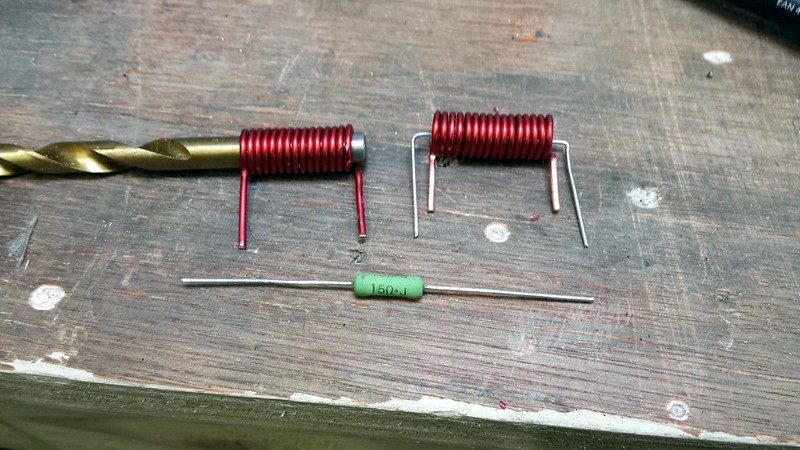
A quick search on Mouser reveals a 2W resistor is about 16mm in length and 5.5mm diameter. Compared to a TDK 1uH SMT ferrite cored inductor rated to 8.5A this is about twice the real-estate.
If this "core" is resistor and any part of it is feromagnetic, than it will be source of distortions ("core" saturation),the same is valid for load used during amplifier tests. Best solution is air inductor, with paralel resistor outside this coil.
I agree.Best solution is air inductor, with paralel resistor outside this coil.
Right. Key qualification 'at audio freqs'.
If the inductor saturates it's become just a length of wire so the amp's once again liable to oscillation.
... Besides the radiation at audio freqs is, as you point out, pretty well negligible because there's no voltage drop.
Yeah, that's persuasive.
If off-the-shelf ferrite-core "RF chokes" had higher current ratings (say 25A instead of 10A for a typical 1uH value) then I might say, well, we don't need to worry about saturation. But there's not a lot of margin with a 10A rated part.
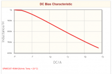
Since the off-the-shelf ferrite cored inductors have air gaps, they don't seem to saturate particularly abruptly. For example here's one from TDK.
Its certainly delivering significant inductance even at 24A. This is a (roughly) 7mm square unit, a considerable real-estate saving over an air core coil with 2W resistor beside it.
Its certainly delivering significant inductance even at 24A. This is a (roughly) 7mm square unit, a considerable real-estate saving over an air core coil with 2W resistor beside it.
Attachments
About 0,015% distortion at 20kHz (THD 20kHz, CCIF19+20..) at 10A peak caused only by inductance nonlinearity. Try it, simply connect such inductor in series with load and measure distortion.
A similar order of magnitude to the distortion induced by speakers being non-linear electrical loads. They draw a non-linear current which when impressed across the impedance of speaker cables, gives rise to voltage distortion.
You forgot to mention ear SPL dependant distortion, and also air compression.🙂 But yes, all distortions are cumulative, so why introduce new distortion, which is not innevitable? Only to save 1cm2 on PCB?
It would depend if that 1cm2 was make or break for a project I guess. 20kHz distortion will be inaudible (40,60kHz harmonics) so I won't worry myself about that.
The saturation non-linearity starts very early, enough to show in a 20kHz harmonic distortion test
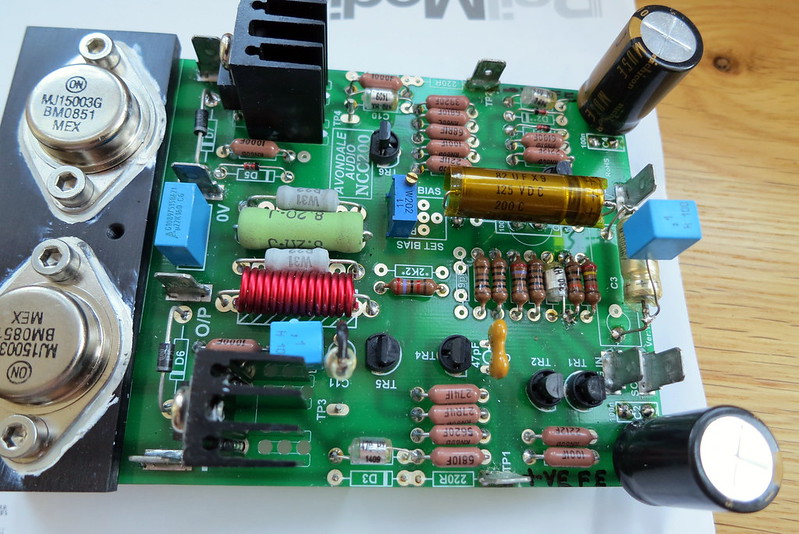
I consider that the wrong place for the output inductor is on the PCB.You forgot to mention ear SPL dependant distortion, and also air compression.🙂 But yes, all distortions are cumulative, so why introduce new distortion, which is not innevitable? Only to save 1cm2 on PCB?
It should be located away from the amplifier, especially the input and away from the chassis metal.
That makes the best place somewhere in the cable between the amplifier and the output terminals.
There it does not use up any PCB space.
Good point AndrewT
They are easy enough to make though and they dont take up much space on the NCC200 board
 voyager 2 by Alan Towell, on Flickr
 IMG_1651 by Alan Towell, on Flickr
Alan
They are easy enough to make though and they dont take up much space on the NCC200 board
voyager 2 by Alan Towell, on FlickrIMG_1651 by Alan Towell, on FlickrAlan
@337alant, what's the red wire called and where do you get it?
The math -- which I should have done before posting in the first place, oops -- strongly suggests output inductors could be audible:
A 1uH inductor at 10kHz has an impedance around 0.05 ohms. The voltage that appears across the inductor is about 1% of the voltage appearing at the load. Suppose the inductor makes 1.5% distortion when measured at the inductor itself (seems totally possible) then if you measure at the load you would see about 0.015% distortion, the exact number BV quoted above. That level of distortion is starting to get audible, yuck.
I'm struck by the similarity between the output inductor, whose distortion is audible even though it's so small we can't hear the HF roll off, and the DC-blocking cap in the NFB path, whose distortion can be audible even if it's large enough that there's no appreciable LF roll off. Sucks to have sensitive ears!
The wire is called enameled wire. RS have it as Block Hookup & Equipment Wire
The issue with the HF distortion caused by the output inductor is that it is going to give you bad magazine review scoring on a full power at 20kHz test. This is totally unrealistic for music, but intermodulation with high current low frequency signals will exist
The issue with the HF distortion caused by the output inductor is that it is going to give you bad magazine review scoring on a full power at 20kHz test. This is totally unrealistic for music, but intermodulation with high current low frequency signals will exist
- Home
- Amplifiers
- Solid State
- ferrite-cored output inductor on a class AB amp?