No the circuit matches the differential input to be as close to each other as possible. The output is a resistor based scale of this. when there is a differential difference at the input nodes the circuit has to do something. when not it's action is accomplished. With feedback action is done when output matches to the scale of the feedback. the way you get the subtraction is through V-I conversion over the input pair input signals are twisted 90 degrees, this is then fed back into the back side of the differential V-I and twisted additional 90 degrees, so the action is, the needed subtraction of the OLG to the desired gain, set by the resistor scale. The circuit can't 100% match the two inputs as there's not sufficient slew rate and not sufficient gain, and the two signals at the input nodes are shifted some nano-seconds in time. (time is a non issue for audio)
And yes it has something to do with lowest state of energy. because when there is a differential difference at the two input nodes the circuit has to do something. Of Course in real life the circuits is always doing something as nothing will ever be steady, The circuit produces signals (noise) for itself to correct all the time, so there will always be some differential voltage to process.
Mike you're mightily confused again. At one point you made a lot of sense. Wat happened?
Jan
Please read again, this is ecactly The same I wrote a while back in the old thread, it's the mechanism of the feedback. In a differential circuit it's the differential that matters. You made a example with an op amp where you had 500 times gain and showed how that resulted in a differential voltage, off course if you had 10000 times gain the differential voltage would be some 20 times less, and if the circuit was ideal the the differential voltages would match each other 100%, this all makes total sense. But how does the circuit know this balance.. It does that by using all excess gain to try to match the two input nodes to each other. Feedback needs a goal, that goal can only be as low as possible differential voltage. That is the only common denominator everything else is derived from that.
Last edited:
No it does not.You were saying this a few weeks ago, were corrected and seemed to understand, but now you are back to your former confusion. The circuit actually matches the differential inputs to be as far apart as is necessary.MiiB said:No the circuit matches the differential input to be as close to each other as possible.
I'm not sure where your two 90 degree phase shifts come from. I can't really comment on something which is so vague that I can't understand it.
"Lowest state of energy" is not a helpful concept to use here. It might impress people who have learnt some physics words, but not what they mean and the appropriate contexts in which to use them.
The circuit does not know anything.MiiB said:But how does the circuit know this balance.
Feedback has no goals, no ambitions, no hopes, no dreams.Feedback needs a goal
Anthropomorphism is a poor way to analyse circuits. I grant you that anthropomorphic language may sometimes be loosely used between experts but they all know that they don't mean what they are saying.
Ok, The circiut seek to match the gain set by the feedback ratio, it does that by throwing away the excess gain... It's the excess gain the defines the differential difference. This action is done by matching the two inputs the best possible. Then the output signal is a scaled copy of the input. This is the only way it can work. The only way the feedback can make the 1. or so order OLG linear.
Please read again, this is ecactly The same I wrote a while back in the old thread.
Yes I know, and I thought you moved ahead after many explanatory posts.
At one time you had a post and I thought - yes he gets it!
Ohh well.
Jan
MiiB/DF96/Jan--the more I read you guys go back and forth, the more the disagreements look like language/descriptive differences than circuit theory.
MiiB/DF96/Jan--the more I read you guys go back and forth, the more the disagreements look like language/descriptive differences than circuit theory.
I don't think so, but I get tired of it anyway. I'm out.
Jan
All this talk give me a idea 😉.
maybe this have already been discussed elsewhere, if so I am sorry but I think this could be useful to understand the open loop gain of the TMC ,
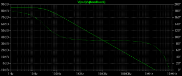
It is possible to get the open loop gain of an amplifier by measure the diference between the inputs of the amplifier in close loop, this is not very accurate especially in the higher frequencies, but is good enough to have an Idea how the open loop gain behaves.
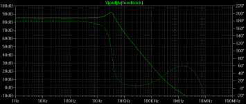
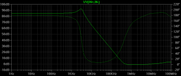
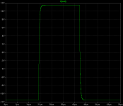
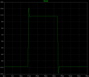
In this example I measure the open loop of a TPC amplifier, the second image is the open loop gain measurement, and the third is the inverse of the diference between the inputs of the closed loop amplifier.
maybe this have already been discussed elsewhere, if so I am sorry but I think this could be useful to understand the open loop gain of the TMC ,
It is possible to get the open loop gain of an amplifier by measure the diference between the inputs of the amplifier in close loop, this is not very accurate especially in the higher frequencies, but is good enough to have an Idea how the open loop gain behaves.
In this example I measure the open loop of a TPC amplifier, the second image is the open loop gain measurement, and the third is the inverse of the diference between the inputs of the closed loop amplifier.
Attachments
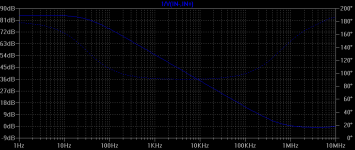
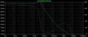
This is the same but with the simple miller compensation. the first measured in open loop and the second in closed loop. the phase is only equal between open and close until 20Khz .
Attachments

And now the TMC,
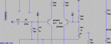
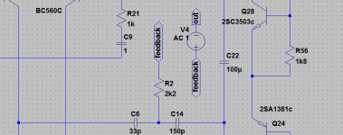
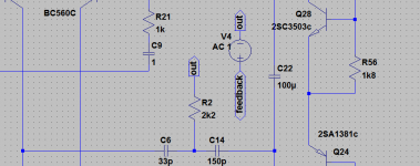
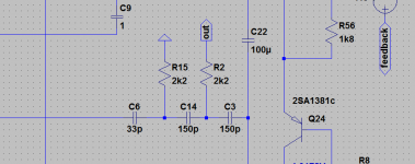
the open loop measurement was made by putting the resistor of the T compensation network after the open loop probe, as you can see that is very different from the measurement of the closed loop.
second image the open loop measurement, third is the closed loop.
the open loop measurement was made by putting the resistor of the T compensation network after the open loop probe, as you can see that is very different from the measurement of the closed loop.
second image the open loop measurement, third is the closed loop.
Attachments

I think that the conclusion we can take from this, is that for evaluate the stability of the TMC amplifier one must use the method in #152, what you guys think ?
2poleTMC
If we measure stability of TMC like in #152 , is possible to include the amplifier output stage in the 2 pole miller compensation and the amplifier is stable, a 2poleTMC .
I have made some stability tests with closed loop and the amplifier with the 2poleTMC seems as stable as the TMC.
If we measure stability of TMC like in #152 , is possible to include the amplifier output stage in the 2 pole miller compensation and the amplifier is stable, a 2poleTMC .
I have made some stability tests with closed loop and the amplifier with the 2poleTMC seems as stable as the TMC.
Attachments
Amplifier with 8ohms with a 22n capacitor in parallel at the output.
with 10n all amplifiers show no sign of oscillation or with a 1uH inductance at output.
First the simple miller
second the 2pole miller
third the TMC
fourth the 2poleTMC
with 10n all amplifiers show no sign of oscillation or with a 1uH inductance at output.
First the simple miller
second the 2pole miller
third the TMC
fourth the 2poleTMC
Attachments


Last edited:
Bigger is better 
An externally hosted image should be here but it was not working when we last tested it.
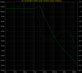
Sergio, what you measure and calculate is the excess gain. Its a representation of the extra gain you have, that can be used for feedback correction.
It's also very close to the level of accuracy your amplifier can reach, like your distortion products are some 85 dB down over a wide range of frequencies.
It's also very close to the level of accuracy your amplifier can reach, like your distortion products are some 85 dB down over a wide range of frequencies.
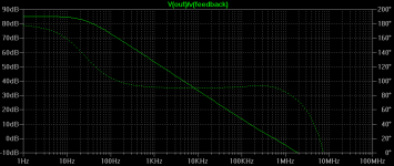
The objective was to try to understand how is the open loop of the TMC amplifier, because depending on including or not the inner feedback loop in the gain probe the outcome is very different.
The first image is the TMC with the inner miller loop included in the gain probe
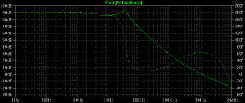
the second image is with the resistor from the TMC network connected directly to the output of the amplifier and not included on the gain probe.
The first image is the TMC with the inner miller loop included in the gain probe
the second image is with the resistor from the TMC network connected directly to the output of the amplifier and not included on the gain probe.
Attachments

- Status
- Not open for further replies.
- Home
- Amplifiers
- Solid State
- Feedback loop speed