Yeah I guess I haveto rethink this, but my brain can work only in time sequence and
so it's sometimes not easy to understand a FB mechanism in details.
And could you please explain about the 90° phase shift to mentioned
earlier inside a single transistor between input voltage/output current?
so it's sometimes not easy to understand a FB mechanism in details.
And could you please explain about the 90° phase shift to mentioned
earlier inside a single transistor between input voltage/output current?
Sorry I wasn't precise: I just wanted to highlight that when we see an OL bode and a 90° phase
shift @ 10Hz it's only like that because its made by applying just a tiny little input level
driving because we cant measure it with a large (normal audio level signal) due to the huge gain.
And so the internal capacitances will have a huge effect. In CL we already can apply normal driving
and in that case we can "overdrive" the OL amp because we assume the FB loop will reduce it in time.
Conclusion/final question: if an opamp could be drived in OL to have an unlimited output level,
driving it with the same voltage level as in CL mode would it still have a 90° phase shift @ 10Hz?
No that is not correct, the (relative) impact of C is independent of signal level (below slew limiting). MiiB has it right a few posts up.
Jan
The compensation capacitor's effect is independent of the signal level below clipping, since this is a linear circuit.
So, if the op amp had unlimited output swing, the open loop amplitude response and phase response
would still be the same. It's the overall feedback that changes those.
Just to remind you that the amp is non liniar. If it were liniar then you could succesfully model the whole thing as a differential amplifier that receives Signal on non-inverting input and Signal/f on the inverting one, where f is a function of frequency. No loopback mental gymnastics needed. Just a differential amp.
Just to remind you that the amp is non liniar. If it were liniar then you could succesfully model the whole thing
as a differential amplifier that receives Signal on non-inverting input and Signal/f on the inverting one,
where f is a function of frequency. No loopback mental gymnastics needed. Just a differential amp.
This is all linear modeling. The op amp's open loop model (a low pass filter) can be included in the equations
for the closed loop response. I did that in the 70s on my IBM AT while modeling op amp nfb RIAA circuits.
I still have some of the curves in my files, if you're interested. The AD797 was the best one of course, btw Scott.
Sure. But as soon as you want to take the non-liniar character of the amp into consideration, function f (in Signal/f) depends not only on frequency, but also on the signal itself. And it all goes down from there.
Sure. But as soon as you want to take the non-liniar character of the amp into consideration, function f (in Signal/f)
depends not only on frequency, but also on the signal itself. And it all goes down from there.
That's still linear behavior, and can be written in a closed-form equation.
If you like, I can work out an example equation and email it to you.
Maybe what Kirchhoff is getting at is that the simplified original (Black) feedback equation assumes a linear amplifier. Later models, including Baxandall's and B. Putzeys' F-word article, include non-linear elements inside the amplifier.
All good fortune,
Chris
All good fortune,
Chris
Last edited:
Maybe what Kirchhoff is getting at is that the simplified original (Black) feedback equation assumes a linear amplifier. Later models, including Baxandall's and B. Putzeys' F-word article, include non-linear elements inside the amplifier.
All good fortune,
Chris
Exactly. If the Amplification factor is also variable with the signal amplitude (not only with signal frequency), then one has to check the work of Mr. Lyapunov. As Fourier, Bode and Nyquist don't help anymore.
Coming back to the thread's subject, I suggest the OP to keep doing some of the simulations in time domain, preferably for a family of input signal amplitudes.
The amplifier don't give a s*** about linearity or frequency for that matter it only deals with differentials. When the differential shifts absolute voltage to GND, then the slew rate af the system gets smaller and the ability to correct the signal will be diminishing, you loose precision and the resulting waveform is distorted. You also get distortion from "mixed mode" operation, like if you bias you differential with resistors as opposed to a current source, then he signal induced current variations also alters the voltages and currents in the stage. So in principle the signal changers the work line and thus modulates the gain with the signal, which then again changes the ability to correct the signal. (Still if you look at the OLG and correlate that to distortion figures, then you'll see a remakbly good coherence, like if you have 60dB excess gain at 20KHz then your amplifier wil have app 0,1% Distortion... Give or tale... A little)
Maybe what Kirchhoff is getting at is that the simplified original (Black) feedback equation assumes a linear amplifier. Later models, including Baxandall's and B. Putzeys' F-word article, include non-linear elements inside the amplifier.
All good fortune,
Chris
I don't think that is true. Black was well aware that amps are nonlinear in your sense that they create harmonic frequencies and that fb improves that. The requirement for fb is that the amp is a linear system meaning it is time-invariant.
I made a simple experiment in Spice with the ideal opamp about the FB.
I attach the results, please help me to analyze it.
The images in order:
So there will be a bigger voltage in case of internal Cs have to be defeated.
Maybe this 10R-10n is a bit extreme but helps to magnify the basic mechanism.
So is ther something wrong with this experiment/analyzation?
Does it differ in any way related to a real FB amp of ours in its operation?
I attach the results, please help me to analyze it.
The images in order:
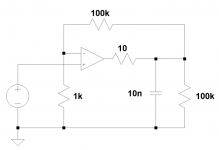
- schematic: simple non-inverting layout with gain = 100 + "internal" capacitance added explicitly
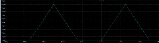
- input: 100uV/1ms (very slow...) slope up and down (twice)
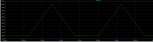
- output: input amplified x 100
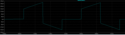
- opamp input: just as I expected: some "overdrive" to charge the "internal" C to provide a correct phase response @ output
So there will be a bigger voltage in case of internal Cs have to be defeated.
Maybe this 10R-10n is a bit extreme but helps to magnify the basic mechanism.
So is ther something wrong with this experiment/analyzation?
Does it differ in any way related to a real FB amp of ours in its operation?
Attachments
Voldtage does NOT defeat capacitance, you made the op amp oscillate (overshoot the square) by forcing it to drive a capacitative load it's not suited to. Change the output R to 100 ohm and you'll dampen the ringing. With the external capacitance you really try to drive close to a short, the op amp can't deliver the current to do that.
Internally your amplifier primarily works with current modulation. Voltage is really not desired. You steer the input with voltage, then charge migrates through the base, then it becomes current, (the operating DC and the modulated signal current) it's also current that pulls the VBE (bias spread) up an down and thus forms the voltage modulation to drive your OPS. What capacitance does, is that it limits the slew rate of the openloop amp an thus reduces the possible gain with frequency. This is how the 1 order curve of the OLG develops.
Internally your amplifier primarily works with current modulation. Voltage is really not desired. You steer the input with voltage, then charge migrates through the base, then it becomes current, (the operating DC and the modulated signal current) it's also current that pulls the VBE (bias spread) up an down and thus forms the voltage modulation to drive your OPS. What capacitance does, is that it limits the slew rate of the openloop amp an thus reduces the possible gain with frequency. This is how the 1 order curve of the OLG develops.
Last edited:
I made a simple experiment in Spice with the ideal opamp about the FB.
I attach the results, please help me to analyze it.
The images in order:
So in my view if there is FB phase can only be corrected with a bigger drive @ input.
- schematic: simple non-inverting layout with gain = 100 + "internal" capacitance added explicitly
- input: 100uV/1ms (very slow...) slope up and down (twice)
- output: input amplified x 100
- opamp input: just as I expected: some "overdrive" to charge the "internal" C to provide a correct phase response @ output
So there will be a bigger voltage in case of internal Cs have to be defeated.
Maybe this 10R-10n is a bit extreme but helps to magnify the basic mechanism.
So is ther something wrong with this experiment/analyzation?
Does it differ in any way related to a real FB amp of ours in its operation?
Nice experiment. I think I see what you are getting at. As long as the output is not up to what it is 'supposed' to be (cap still charging up) the feedback signal is also lower (because it's a fraction of Vout) then what it is 'supposed' to be. That means that the effective Vin (difference between input and feedback signal) is larger than what it is 'supposed' to be. That is nicely illustrated in your circuit.
But I don't think you should say 'FB phase can only be corrected with a bigger drive @ input'. There is no intentional correction (if you get my meaning) present - it's just some voltages that go up and down depending on what's going on in the amp.
Jan
Yeee Jan! Finally! This is exactly what I meant! 🙂
MiiB: of course not voltage in itself defeats the C.
Only a higher current can charge a given RC faster.
But if you want to "push" a bigger current on a given RC you have to apply a bigger voltage to it.
Which is happening automatically with FB exactly as Jan wrote: untill the internal C isn't
charged the FB does/can not "stop" itself at the input so a bigger controll voltage is appearing.
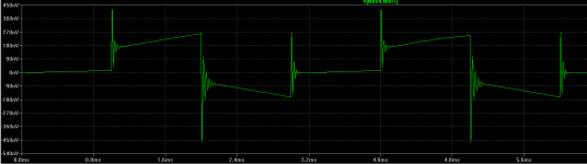
Well this ringing is still not clear to me... But the output R is 100R when it's ringing!you made the op amp oscillate (overshoot the square) by forcing it to drive a capacitative load it's not suited to. Change the output R to 100 ohm and you'll dampen the ringing. With the external capacitance you really try to drive close to a short, the op amp can't deliver the current to do that.
I tried and it works just the opposite way: If I set the output R to 1R this IDEAL
opamp can easily drive this 100n capacitive load (this needs only 1uA at this level!).
The ringing appears if it has to drive via a 100R "internal output impendace".
So the question: why it produces a ringing..?
Well this ringing is still not clear to me... But the output R is 100R when it's ringing!
I tried and it works just the opposite way: If I set the output R to 1R this IDEAL
opamp can easily drive this 100n capacitive load (this needs only 1uA at this level!).
The ringing appears if it has to drive via a 100R "internal output impendace".
So the question: why it produces a ringing..?
I think the reason is that when you use a larger R the roll-off starts earlier meaning more phase shift at the point where the OL gain drops to one. Classical case of approaching instability due to not enough phase margin illustrated by increased ringing...
Jan
Okay, but the questuion is: why..? 🙂when you use a larger R the roll-off starts earlier
- Status
- Not open for further replies.
- Home
- Amplifiers
- Solid State
- Feedback loop speed