what causes this 90° phase shift in OL even at low frequencies close to DC?
That's caused by the dominant pole due to the capacitor on the voltage amplifier stage.
Since that pole is usually at very low frequencies, the phase shift through most of the audio band is -90 degrees,
while the amplitude roll off through the same range is -20dB/decade.
Actually, Sergio, that pulse has a lot of hf energy outside the audio band.
Might be actually be useful when trying to trigger oscillations. Filter it an you'll never know.....
Error correction
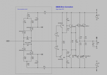
Today I have test a error correction that I designed, it is based on hawksford ideas.
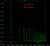
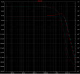
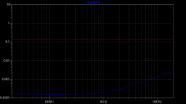
The circuit is very efective in lowering the harmonic distortion of the output stage, here is the fft of a 20v 1KHz sine with a output impedance of 4 ohms.
The distortion of the output stage without Error correction is 0.084% with error correction is 0.00033% .
edit: the capacitor C6 is a error
Today I have test a error correction that I designed, it is based on hawksford ideas.
The circuit is very efective in lowering the harmonic distortion of the output stage, here is the fft of a 20v 1KHz sine with a output impedance of 4 ohms.
The distortion of the output stage without Error correction is 0.084% with error correction is 0.00033% .
edit: the capacitor C6 is a error
Attachments

Last edited:
The delay is also very low at only 5ns. It also behaves better than the 2 pole compensation in the impulse test, showing only small overshoot at the end of impulse (34mV in a 20V signal).
Attachments
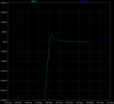
This is the phase and gain of the output stage with (red trace) and without Error correction. with error correction the gain is much closer to 0db as a perfect output stage should be.
Attachments
Last edited:

With current sources.
The idea is simple, the mosfets differential pair compare the output of the output stage with the input and create a error current that flow by error resistor, and this error voltage will add to the source voltage. C1 is for open loop compensation.
The idea is simple, the mosfets differential pair compare the output of the output stage with the input and create a error current that flow by error resistor, and this error voltage will add to the source voltage. C1 is for open loop compensation.
Attachments

Last edited:
Looking good! I have been playing with Hawksford EC as well, similar results. The paX amplifier published by Elektor was a H.ec design.
The limit in the correction is the accuracy of the correction circuit. It must have the exact error gain (1 x in my case) and maintain that over frequency. Easy in LTspice, hell in practise. For example, for a 40dB error reduction you need an accuracy of better than 1%, and a bandwidth of the correction circuit 100 x the highest freq you want to correct. A tall order!
The limit in 'normal' feedback which is formed by the loop gain you can have before instability, is replaced in ec by the limit in accuracy and bandwidth.
Jan
Looking good! I have been playing with Hawksford EC as well, similar results. The paX amplifier published by Elektor was a H.ec design.
The limit in the correction is the accuracy of the correction circuit. It must have the exact error gain (1 x in my case) and maintain that over frequency. Easy in LTspice, hell in practise. For example, for a 40dB error reduction you need an accuracy of better than 1%, and a bandwidth of the correction circuit 100 x the highest freq you want to correct. A tall order!
The limit in 'normal' feedback which is formed by the loop gain you can have before instability, is replaced in ec by the limit in accuracy and bandwidth.
Jan
We discussed that Sergio EC design in this thread: http://www.diyaudio.com/forums/solid-state/260308-gainwire-ngnfb-classb-poweramp.html
Yes. In my design I used an IC current conveyor (AD844) rather than a discrete one for a bit better accuracy but the concept is the same. I noticed that thread died a quiet dead a few years ago.
Jan
Jan
Sorry I feel my question is still not answered (or just I dont get it... 😱)That's caused by the dominant pole due to the capacitor on the voltage amplifier stage.
Since that pole is usually at very low frequencies, the phase shift through most of the audio band is -90 degrees,
while the amplitude roll off through the same range is -20dB/decade.
What casues the difference in phase shift between OL and CL
operation (especially if the amp works ALWAYS and just in OL)?
My guess was: in OL there is just very small signal input because of the HUGE gain.
Therefore the internal capacitances have a MUCH bigger (d)effect on the phase transfer.
In CL (analysed in transient mode thinking which I like the best 🙂) at the
begining it works as a simple OL, BUT there is a large input signal (voltage
level and current capacity) for a short period of time which can drive these
internal capacitances much better. Then if this is done the input signal can
reduce itself via the FB substraction at the begining point.
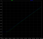
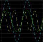
Example: see the attachment for discussing the voltage levels vs frequency topic. The signals:
Light blue: 2Vp 1kHz
Green: 1Vp 1kHz
Yellow: 1Vp 2kHz
As it seems if we want to achieve a slope like the 2kHz 1V signal needs (first 45° part)
we can also with a 1kHz 2V signal so as it seems signal speed is also dependent to voltage level.
And thats why FB can "correct" the phase in CL mode.
Does that make any sens?
Attachments
No. Internal capacitances have exactly the same effect. The difference is that the input signal seen by the OL amplifier is phase shifted from the input signal sent by the user to the CL amplifier. Remember, the subtraction which takes place at the feedback summing node is a vector/phasor subtraction, not a simple scalar subtraction. In most cases the signal is not only greatly reduced in size but it is also shifted by approximately 90 degrees.Cortez said:My guess was: in OL there is just very small signal input because of the HUGE gain.
Therefore the internal capacitances have a MUCH bigger (d)effect on the phase transfer.
Last edited:
But analysing it in time at the very first moment there is no FB signal at all!
Just the input signal "proceeding" forward.
FB signal will be provided ONLY at the end of the forward section.
(Altough we can say untill then the "0" is the FB signal.)
And if so until then the stage are working in OL mode.
So the phase shift must be the same.
The only difference is the input voltage level!
I am sure the feed forward section doesnt have a 90° phase shift @ 10Hz...
And thats because the higher voltage @ the input.
Even the "phase" cannot be interpreted in an absoulte way as you can see its related to the signal level as well.
But the time for the feedback signal to arrive is so infinetly small that the input has only changed close to nothing. So what you have with is a realtime level matching where the two inputs of the differential matches as close as possible. If you cut the action up, then the differential signal is subtracted by 2 x 90 degrees phase sift, one 90 degrees from input and the next 90 degrees from feed the shifted signal back into the loop. This is how the differential gets rid of the excess gain and how the system is made linear. It's a dV/d(t) system with infinitesimal small adjustments. Limits for precision are: gain(which is limited by capacitances) slew rate (also limited by capacitance) and delay (which is pretty much set by distance and the speed of current, app 2/3 of the speed of light). For Audio time is not an issue.
So in a system with FB with we are generating a "control signal" based on the input signal
but which is in shape completely different from the input signal just to defeat the internal deffects.
The principle is to apply the max our system is able to produce -> untill we say its enough...
And we say stop when the output voltage level achieved a certain (proportional) level related to the input one.
And the reason we can do that is because we have an extra energy (driving potential) compared to
expected final signal level. And we suppose that the transfer function is kind of a one direction
type (I dont know a right expression to that right now): If we want more output level we have to
apply more driving @ the input because even if there are some capacitive problems inside we can
defeat it with more energy applied. And gain isn't by all means related to this mechanism at all!
The input signal and the PS part is enough to achieve that. Gain is only neccesary because our
original need is voltage amplification (due to typical signal levels vs loudspeaker energy needs)
but from the control theory point of view if the task is just to produce a perfect output signal
via a not-ideal buffer wich has an internal phase shift and which can be highly driven, then a large
input signal + FB is enough to defeat this phase problem. In the hifi world we dont have any kind
of input signal level so thats why we have to have gain to have access to this extra energy...
Sorry I wasn't precise: I just wanted to highlight that when we see an OL bode and a 90° phaseBut the time for the feedback signal to arrive is so infinetly small that the input has only changed close to nothing.
shift @ 10Hz it's only like that because its made by applying just a tiny little input level
driving because we cant measure it with a large (normal audio level signal) due to the huge gain.
And so the internal capacitances will have a huge effect. In CL we already can apply normal driving
and in that case we can "overdrive" the OL amp because we assume the FB loop will reduce it in time.
Conclusion/final question: if an opamp could be drived in OL to have an unlimited output level,
driving it with the same voltage level as in CL mode would it still have a 90° phase shift @ 10Hz?
Last edited:
when we see an OL bode and a 90° phase shift @ 10Hz it's only like that because its made by applying just a tiny little input level
so the internal capacitances will have a huge effect. if an opamp could be drived in OL to have an unlimited output level,
driving it with the same voltage level as in CL mode would it still have a 90° phase shift @ 10Hz?
The compensation capacitor's effect is independent of the signal level below clipping, since this is a linear circuit.
So, if the op amp had unlimited output swing, the open loop amplitude response and phase response
would still be the same. It's the overall feedback that changes those.
Last edited:
Cortez, you have to realize that the amplifier is in reality only dealing with the differential signal, as the input and feedback are summed exactly at the input, so the amplifer has only to deal with a signal that is a thousand times less than the linear gain (assuming you have 60 dB excess gain. And yes the 1 pole filter is because of the capacitances exhausting gain from the transistors, mind you that the 120 dB or so you have at the lowest frequencies amounts to a whooping 1 million times amplification. So the modulated currents in openloop becomes filtered by the small capacitances of the devices and you get this sloping 1.order response. This with the sloping gain is also the reason why the corrective gain drops, and the same you see in the ability to make an exact scale of the input signal, result is an increase in distortion . (There are more reasons for distortions as well)
- Status
- Not open for further replies.
- Home
- Amplifiers
- Solid State
- Feedback loop speed