Jan, at first glance I think that the increase loop gain at audio frequency and the decrease in current in the miller capacity can be the reasons for that excellent result.
The 2 pole has 30db more gain at 20khz, and the current in the miller cap is only 3uA, in the simple miller is 80uA. This charging and discharging of the miller cap is for sure the main culprit of the delay in the amplifier.
Agreed, yes that's a convincing explanation.
Jan
this thread could be improved by people learning the "non/minimum phase" distinction
the wikipedia article starts with discrete time - you should want to understand the continuous time presentation lower down
https://en.wikipedia.org/wiki/Minimum_phase
does require significant background to read that and proceed to the Bode Integrals that show the limits, how much "essential" limit comes from non-minimum phase in a feedback loop
but a very simple few things to get are that Laplace transfer function descriptions of linear gain blocks can be factored into minimum phase and non-minimum phase parts
non-minimum phase is associated with Right half plane zeros of the openloop transfer function
"true delay" would have infinite pairs of left plane poles mirrored by right plane zeros evenly spaced on a pair of vertical lines in the s-plane
and that any non-minimum phase parts constitute a loss of potential feedback gain that could otherwise in its absence be used without stability problems
B J Lurie is one of the best I know of for information on how to actually design with Bode Integral limits
Dr. Boris J. Lurie's Homepage: Classical Feedback Control
his site has a book chapter on loop gain shaping online and some other material
Appendix 11, Classical Feedback Control
I highly recommend his book - but only after you've managed good control theory intro course and all of its prerequisites
Last edited:
One thing is to physically understand the mechanism, an other thing is to fully grasp the math involved. Like I can fully envision and by hand calculate strains and deflections in most mechanical structures, but when You get to a hole or a sudden change of dimension empiric driven rules take over for manual dimensioning, or for accuracy you're left with FEM and computer based solutions. Point is that you don't need to do the math in order to be a good and efficient engineer, but you really need to understand the limits of the tools you employ in order not to become a dangerous one.
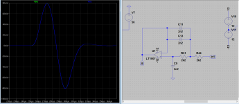
Here my fiddling with spice and feedback It seems that the corrections not only are in amplitude but also in time. That the delay you'd expect simply is not there, or below the capability of my simulator. I find that intriguing. Feedback works as an inverse filter of the OLG typical 1.order slope.
Here my fiddling with spice and feedback It seems that the corrections not only are in amplitude but also in time. That the delay you'd expect simply is not there, or below the capability of my simulator. I find that intriguing. Feedback works as an inverse filter of the OLG typical 1.order slope.
Have made some tests with complex signals and impulses instead of steady state signal , and the 2 pole comp. starts to misbehave and as Michael said there is time and amplitude distortions. Tomorrow I will post some pictures of the tests. Good night.
Correct me if this explanation is wrong:
In OL mode there is just small signal mode: small input signal, current, etc.
Thats why even in the lower frequencies there can be a 90° phase shift due to internal capacitors.
In CL we (can) apply a "large" input signal (voltage/current) but just for a short time.
Exactly to the time until the FB stops it and so this transient bigger power can charge the internal caps, etc.
So thats how power can "defeat" time... 🙂
Its like the output stage "phase delay" when stressed with a capacitive load.
If you have the (current) capacity you can defeat the delay.
http://www.control.lth.se/media/Education/DoctorateProgram/2012/Delays/Lectures/lect01.pdf looks pretty good to me for the still Uni EE technical level
good points to start, pages ~35-55 gets serious about what a continuous time delay looks like in various common control design plots and shows modeling as pole-zero transfer functions
good points to start, pages ~35-55 gets serious about what a continuous time delay looks like in various common control design plots and shows modeling as pole-zero transfer functions
How well does the Laplace based theory work with non-linear systems? Oh, wait, it says there on the first page.... 😛
Correct me if this explanation is wrong:
In OL mode there is just small signal mode: small input signal, current, etc.
Thats why even in the lower frequencies there can be a 90° phase shift due to internal capacitors.
In CL we (can) apply a "large" input signal (voltage/current) but just for a short time.
Exactly to the time until the FB stops it and so this transient bigger power can charge the internal caps, etc.
So thats how power can "defeat" time... 🙂
Its like the output stage "phase delay" when stressed with a capacitive load.
If you have the (current) capacity you can defeat the delay.
In open loop most amplfiers has a frequency response close to that of a 1.order filter, result is 90 degrees phase shift like all 1.order filters have, when you close the loop you make it linear by using the excess gain for correction. This basically nulls the phase shift.
On what has become "The Feedback Speed" thread, let me pick some brains on this amp I saw in The Absolute Sound:
Soulution 711 Stereo Amplifier, 701 Monoblock Amplifier, and 725 Full-Function Preamplifier | The Absolute Sound
Soulution 501 Monoblock Amplifier: First Listen | The Absolute Sound
Soulution 710 Stereo Amplifier, 700 Monoblock Amplifier, and 720 Preamplifier (TAS 199) | The Absolute Sound
Now I know little to nothing about electronics, loudspeakers are more my area, but as a general rule I'm very skeptical of any manufactures claims of revolutionary technology without independent measurements.
I know but these are "just" the consequences, but how it's done "down there"? Is it somehow as I wrote? What and how makes from a 90° phase shift an almost 0°?In open loop most amplfiers has a frequency response close to that of a 1.order filter, result is 90 degrees phase shift like all 1.order filters have, when you close the loop you make it linear by using the excess gain for correction. This basically nulls the phase shift.
no the mechanisms are not a result of amplitude or duration. The phase shifts comes from V-I transformations in the amplifer circuit. When you look at a transistor it's a device where you use a base voltage to modulate the collector/emitter current. The modulated current is directly shifted 90 degrees. Tha amplifer OLG contains two things amplification and filtering, the amplification is linear and the low pass filter holds the phase shift like any other filter would, with feedback you cut away the excess sloped gain (rightly you use it to keep precision in the linear part) and keep tha amplification in a fixed ratio. When the circuit runs out of excessive gain it then becomes a low pass filter again an you see the associated phase shifts reemerging.
Last edited:
Hmm? What? 🙂When you look at a transistor it's a device where you use a base voltage to modulate the collector/emitter current.
The modulated current is directly shifted 90 degrees.
Why would it shift the phase with 90°?
In a transistor the output current is in phase with the input voltage isn't it?
BTW: its not clear to me: what causes this 90° phase shift in OL even at low frequencies close to DC?
Basically the internal miller effect multiplied with every stage "simulating" a
huge C between the input/output nodes from the outside forming an RC filter?
In audio amplifiers there ain't no (significant) "propagation delay".
Don't confuse it with phase lag.
Don't confuse it with phase lag.
I open loop there is a phase shift as the gain slopes like a 1. Order filter. The propagation delay is very low and non significant
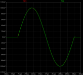
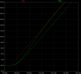
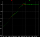
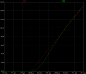
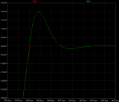
simulation with a single pulse of 20khz
simulation with a single pulse of 20khz, the delay at the start and end of the impulse are not so great in the 2 pole compensation, it start with the same delay as the simple miller compensation and it takes more than a 1us to stabilize, at the end of the impulse the 2 pole comp. also exhibit overshoot
This images show the 2 pole VS simple miller.
Attachments
Last edited:
simulation with a single pulse of 20khz, the delay at the start and end of the impulse are not so great in the 2 pole compensation, it start with the same delay as the simple miller compensation and it takes more than a 1us to stabilize, at the end of the impulse the 2 pole comp. also exhibit overshoot
Actually, Sergio, that pulse has a lot of hf energy outside the audio band. To stay in band you should run that pulse through a 20 or 30kHz low pass first.
jan
- Status
- Not open for further replies.
- Home
- Amplifiers
- Solid State
- Feedback loop speed