Hello everyone, is there a 'simple' way to calculate gain changes with alterations in a feedback circuit?
I have an old Sp8 circuit that takes feedback from through two resistors, one of which is optional to remove for a 10 dB alteration according to the manual. I was wondering if I could reduce by a little less e.g. 5 dB by altering this resistor as opposed to removal.
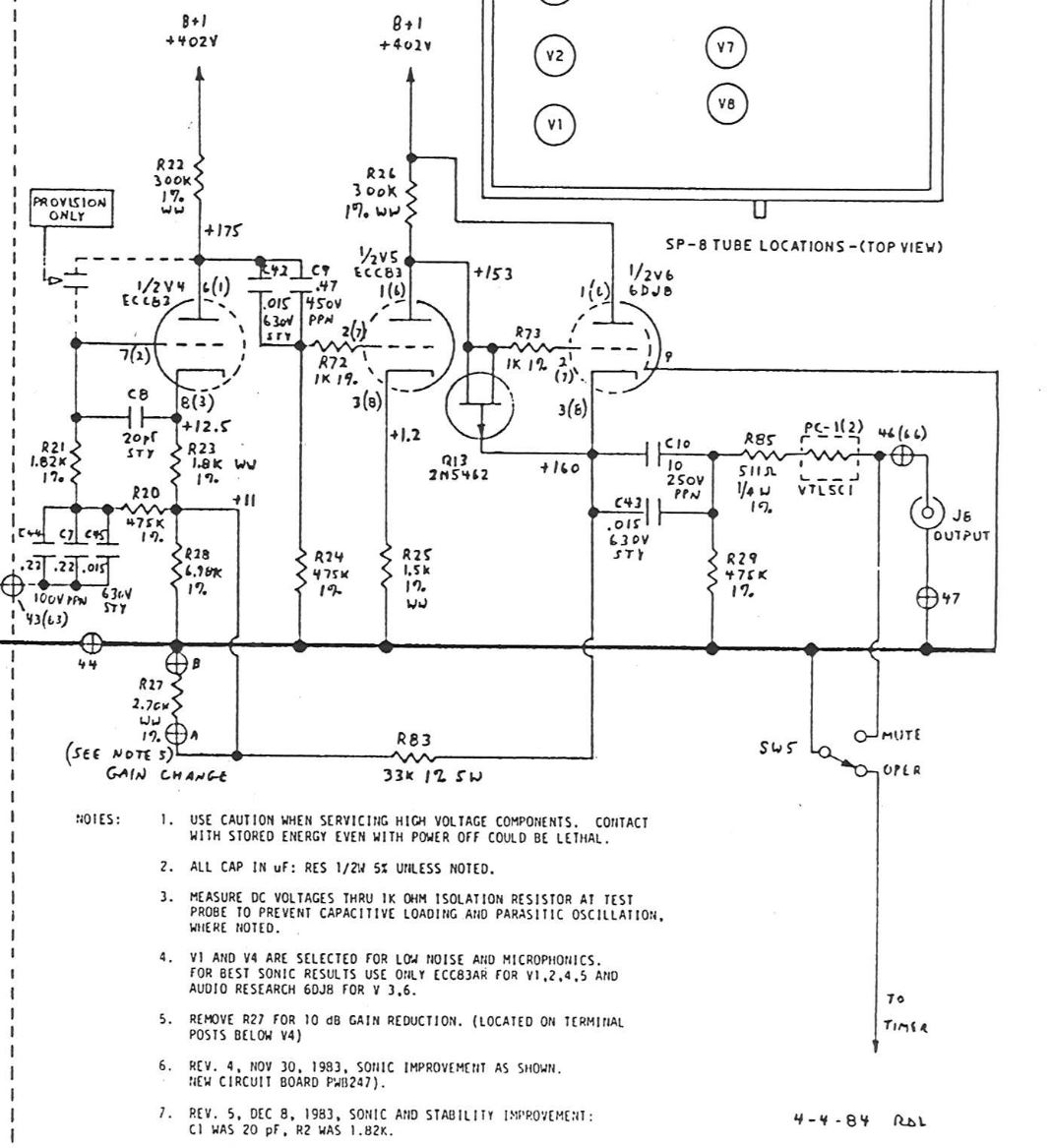
ARCDB is here (last 3 pages are the circuit I have) and there is a note 5. on the circuit diagram about resistor R27 removal for 10 dB gain.
I have also interpreted that more feedback = worse sound, so want to be careful about how much to temper a very high gain preamp with very sensitive speakers. (It still hums a little too much on standby, and I don't use much of the volume know for full listening levels)
Thanks
I have an old Sp8 circuit that takes feedback from through two resistors, one of which is optional to remove for a 10 dB alteration according to the manual. I was wondering if I could reduce by a little less e.g. 5 dB by altering this resistor as opposed to removal.
ARCDB is here (last 3 pages are the circuit I have) and there is a note 5. on the circuit diagram about resistor R27 removal for 10 dB gain.
I have also interpreted that more feedback = worse sound, so want to be careful about how much to temper a very high gain preamp with very sensitive speakers. (It still hums a little too much on standby, and I don't use much of the volume know for full listening levels)
Thanks
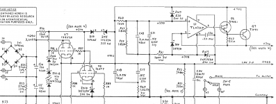
The link is a bit broken, but the relevant part of the circuit is attached. That circuit relies on feedback, with the output cathode follower sharing a resistor with the first stage cathode. I wouldn't be worried about "more feedback = worse sound" in this case. Just try the suggested modification, or if you really only want 5 dB gain reduction then try replacing R27 with an 8.2k (bit of a guesstimate but should be close enough).
Attachments

thanks - oh and how did you manage to get a photo uploaded, I noodled around the site (I am new) and couldn't seem to find how?
Look at this link to see how to upload pictures:
How to attach images to your posts.
This adds them as thumbnails. There is another short step to embed them in the post - after you've uploaded the image, click on "Preview Post" then copy the URL of the attachment. Then click the "Insert Image" icon and paste the URL.
How to attach images to your posts.
This adds them as thumbnails. There is another short step to embed them in the post - after you've uploaded the image, click on "Preview Post" then copy the URL of the attachment. Then click the "Insert Image" icon and paste the URL.
I have one of these in for repair right now. Replace the 1000pF 600V styrene capacitor in the power supply by the 12AT7/12BH7 while you have it apart! If that fails, you're in for a painful repair experience...
thanks - I will do that
Have you taken the optocouplers out of circuit - dramatically better in my system?
Have you taken the optocouplers out of circuit - dramatically better in my system?
I haven't, the SP-8 that I have here is supposed to be repaired and sold, and I'm not sure the new owner would appreciate the mods.
Getting rid of the timer circuit and line voltage muting circuit doesn't seem like such a bad idea though, how's the turn-on thump with the LDRs pulled out?
Getting rid of the timer circuit and line voltage muting circuit doesn't seem like such a bad idea though, how's the turn-on thump with the LDRs pulled out?
I just put the manual mute on and wait 2-3 mins, then play as normal. What is an LDR not sure what you mean here?I haven't, the SP-8 that I have here is supposed to be repaired and sold, and I'm not sure the new owner would appreciate the mods.
I purchased some more optocouplers as they are no longer in production and not that expensive from the US to have on hand, in case I wanted to sell the sp8 in the future and someone wanted to have an original even if it sounded worse...
Getting rid of the timer circuit and line voltage muting circuit doesn't seem like such a bad idea though, how's the turn-on thump with the LDRs pulled out?
The optocouoler looked to be a light dependent resistor, though I didn't examine a datasheet or anything that carefully.
yeah it is, when the mute timer is complete it acts as a short circuit, and when its in warm up it acts as a high resistance, but mine were tired (bit noisy in warm up) and now out of circui: way better quality of sound. I swapped out a resistor to make this work, so this may have also improved the Sound?
Thanks - have got the photo sorted now.
The other sideways approach could be to somehow reduce the sensitivity of the power amplifier with a volume pot at the input or resistance change here / or maybe shunt in someway the output to the speakers. Is this a possibility or a stupid idea to spoil sound quality?
The other sideways approach could be to somehow reduce the sensitivity of the power amplifier with a volume pot at the input or resistance change here / or maybe shunt in someway the output to the speakers. Is this a possibility or a stupid idea to spoil sound quality?
I have one of these in for repair right now. Replace the 1000pF 600V styrene capacitor in the power supply by the 12AT7/12BH7 while you have it apart! If that fails, you're in for a painful repair experience...
Do you mean this one - C31 on the circuit diagram?
Thanks,
Attachments
C34. Maybe I'll have the SP-8 that's here fixed this week from that cap failing, but boy did it blow up a lot of parts!
I think PPR answered your question the gain is roughly R83 / (R27||R28) as this determines the NF. R83 sets most of the current in the cathode follower, but you can vary R27||R28 as the first stage bias floats and R23 sets the current here. Very cleaver circuit avoiding two coupling caps.
Last edited:
Thanks for the advice, and on a similar principle - a friend of mine has an SP10 which is very similar in that it produces 26 dB gain on line stage, it does have a high gain/low gain switch - but sadly looses quality on low gain. He is trialing a different power amp, and the supplier has loaned him an integrated so that he can see both the power amp side and the pre amp; for the power amp he just runs the SP10 into a line input and controls effectively 2 volume knobs to balance the Sp10 to be around 11-12 oclock. SO the question is could he just fit a voltage divider as an attenuator into his normal sensitivity amp. He does not want to change the inside of his amplifier with gain settings.
- Home
- Amplifiers
- Tubes / Valves
- Feedback and Gain