I still think that I am right , lets see if any other person also comments .
You agree that if I have four supplies all have 50,000MFD , now if we connect two of these supplies in series , the voltage doubles and MFD remains 50,000 , please note that there is a difference in connecting caps in series and two DC supplies in series .
regards ,
Rajeev
You agree that if I have four supplies all have 50,000MFD , now if we connect two of these supplies in series , the voltage doubles and MFD remains 50,000 , please note that there is a difference in connecting caps in series and two DC supplies in series .
regards ,
Rajeev
Unless the first 50v Rails are used in class-H arrangement, your caps are connected in series to make the 100v.
Your voltage doubles, capacitance halves and your joules (energy storage ) remains the same.
Another issue, your ESR will go up by 100% as well when connected in series because the ESR is analogous to having a 0.5 ohm (or whatever value) in series with the cap charging the amp, this reduces the efficiency with which the supply can deliver boat loads of current to the load when needed. By using caps in series, you make the resistor double in value (= 1 ohm) further diminishing the capacity of your supply to deliver current. Mind you this phenomenon is separate from the amount of capacitance (which is more related to storage and not delivery). ESR is relevant to the "delivery" of that storage. All that capacitance is of little use if it cannot be delivered efficiently. People remove their 40,000uF caps and put in one low ESR 10,000uf Blackgate for the same reason.
Thats also why people parallel multiple smaller caps to "lower" the ESR, arranging in series makes it worse. Now some people claim that using 2 large caps makes the sound more musical than several smaller caps, but thats another debate. 😉
Another issue you will have is to keep the voltage across both halves of the caps constant at 50v, (unless it is fed from a separate 50v supply from the Transformer), if it is just a single 100v supply (realistically 90v for 100v cap) then the voltage may "float" across the two halves and may end up being 60v on one half and 30v on the other... you could blow that one half. This may or may not apply to your arrangement.
If you want 50,000uF 100v, you'd need 4 sets of 50,000uF @50v per channel. Two paralell, and two in series to get 50,000uF 100v.
This would be duplicated for the second channel and your amplifier would have a total of 100,000uF made from 8 sets of 50,000uF 50v cap arrangements.
Thats what I have always understood it as. 🙂
Your voltage doubles, capacitance halves and your joules (energy storage ) remains the same.
Another issue, your ESR will go up by 100%
as well when connected in series because the ESR is analogous to having a 0.5 ohm (or whatever value) in series with the cap charging the amp, this reduces the efficiency with which the supply can deliver boat loads of current to the load when needed. By using caps in series, you make the resistor double in value (= 1 ohm) further diminishing the capacity of your supply to deliver current. Mind you this phenomenon is separate from the amount of capacitance (which is more related to storage and not delivery). ESR is relevant to the "delivery" of that storage. All that capacitance is of little use if it cannot be delivered efficiently. People remove their 40,000uF caps and put in one low ESR 10,000uf Blackgate for the same reason.Thats also why people parallel multiple smaller caps to "lower" the ESR, arranging in series makes it worse. Now some people claim that using 2 large caps makes the sound more musical than several smaller caps, but thats another debate. 😉
Another issue you will have is to keep the voltage across both halves of the caps constant at 50v, (unless it is fed from a separate 50v supply from the Transformer), if it is just a single 100v supply (realistically 90v for 100v cap) then the voltage may "float" across the two halves and may end up being 60v on one half and 30v on the other... you could blow that one half. This may or may not apply to your arrangement.
If you want 50,000uF 100v, you'd need 4 sets of 50,000uF @50v per channel. Two paralell, and two in series to get 50,000uF 100v.
This would be duplicated for the second channel and your amplifier would have a total of 100,000uF made from 8 sets of 50,000uF 50v cap arrangements.
Thats what I have always understood it as. 🙂
Check the other post .............
Hi Rajeev,
I finally got the hfe tester done. The results are given in the following post
http://www.diyaudio.com/forums/showthread.php?s=&postid=596980#post596980
Note my capacitance tester used 120Hz. It has a 1Khz setting which showed slightly lower capacitance.
If you want a pcb of the hfe tester , let me know. You can set it to read hfe at various collector currents ( up to about 1 Amp ).
At base currents other than 1 or 10 mA you will need to do some maths or rig up a divider before your DMM to directly read
hfe ( for each setting of base current).
Cheers,
Ashok.
caps in series...
...tend to equalize the voltage between themselves through leakage. As the voltage across one rises it will tend to leak a little more, this will ultimately make the voltages on the 2 parts settle at something close to the ratio of the leakage...for DC...
For AC, under high surge conditions, like in a power supply, the cap that has the smaller value will have higher AC voltage across it, and so you cannot use all the voltage that the ratings would imply, be careful...tolerances on electrolytics are not 'tight', nor stable, 2 'identical' caps can be 40% different...so the AC voltages will be 40% different...
Then they need to track each other thermally...in fact they need to be very closely matched in all ways, past, present and future...ie they need to be identical caps, approx. the same age, have been used similarly etc or you run the risk of destroying them both in a somewhat spectacular fashion...plus it's hard to get the sticky stuff off the ceiling.
If you can avoid this situation, I would, but if not, using a pair of modest value serial resistors in parallel with the caps couldn't hurt, joining the caps and resistors at the midpoints...
I do this sort of thing all the time prototyping, but IMHO, not in a 'finished' product, it's just too risky without great attention to detail...
Stuart
Agreed, a series resistor helps. Can you comment on the capacitance issue? Rajeev thinks my analysis is in error, if I am, I'd like to know too. 🙂
K-Amps ,
Thanks for the feedback ,
You write
"Another issue you will have is to keep the voltage across both halves of
the caps constant at 50v, (unless it is fed from a separate 50v supply
from the Transformer), if it is just a single 100v supply (realistically 90v
for 100v cap) then the voltage may "float" across the two halves and may
end up being 60v on one half and 30v on the other... you could blow that
one half. This may or may not apply to your arrangement. "
The above is out of question in my case , also there are no series
resistors , if required I will put one in transformer primary , from your text I
am feeling that I did not convey my idea properly , all that you have
written is applicable only if the caps are in series to the voltage availible
from a single bridge rectifier and transformer secondary winding , hence
I will repeat a part of what I had written again .
This is what I had written ,
" I needed a 62v-0-62v transformer , but I made a transformer with
four 31v windings , I will use four bridge rectifiers & banks of 5x10,000
Mfd 50v caps after each rectifier , like this I will have four independant
supplies , then I will connect two of these in series for each rail and
ground the centre . Like this the caps will be in series but their Mfd will
still remain 50,000Mfd per rail . "
By the above I meant that the transformer has four independant
secondary windings of 31v each , there will be a seperate bridge
rectifier and a bank of caps for each of the 31v winding , Like this I have
four independant powersupplies . Now what I would like to know is how
does it make a differance if I load these supplies individually or all of
them in series together , as long the load on each is the same ?
Ashok ,
Let me know your views too .
Cheers
Rajeev
4 independant supplies only alleviates the voltage sharing issue I talked about.
As it is you will connect the output stages only to the +/- 87vdc rails, which "see" 25000uF to ground not 50,000uF x2.
The ESR issue is still these.
However it will work fine, I do not see any major issues.
As it is you will connect the output stages only to the +/- 87vdc rails, which "see" 25000uF to ground not 50,000uF x2.
The ESR issue is still these.
However it will work fine, I do not see any major issues.
caps in series...
theory: 2 identical caps in series gives you 1/2 the capacitance, I don't know how to enter formulas here, you guys probably know it already, but caps in series use a formula like resistors in parallel...The ESR is definitely the sum of the 2 caps, and if you use all the voltage potential, the total energy is doubled. IIRC energy is prop. to v^2 and C, so half C but 2v gives twice the total energy...
Correct me if I'm wrong, but (ignoring ac-dc rectification details) I think what Rajeev is describing is a quad of ~30v windings being joined to give a 60-30-0-30-60 supply, where the 50 000u are being used between each of the 30v legs. In this case, between adjacent 30v taps, the caps will behave exactly as expected, ie 50 000u, but will only act like 25 000u if one were to look at them from the 62v rails...the voltage balancing is not a problem here, each winding will only contribute a 'safe' potential to each capacitor...
...of course 32v AC rectified is getting pretty close to 50v DC...
Stuart
imo, by using 4 rails you solve the floating voltage problem.
But :
doubling a capacitor means doubling the energy storage.
Capacity is defined as amp seconds per volt, C = A*S/V
The relation between energy and voltage is :
P = C * (V * V) /2
Twice the voltage and twice the energy means the capacity is halved.
Which makes sense because the capacitor resistance is doubled, so current per volt is halved.
Current per volt halved> capacity halved !
Think of the bottom capacitor that has the resistance of the capacitor above it added, same voltage on the cap but the max current is half.
Re: caps in series...
I routinely use 62-0-62 rectified to +/-86. 100vdc seems a bit high (or 31 to 50vdc) 😀
Typically 62 * 1.41414 = 87.67 less 1 volt for rectification = 85.67 add a little bias and the rails come down to around 85vdc per rail. thats good for a 400 watts RMS amp at 8 ohms with good regulation i.e. 1.5kVA or over trafo.
Stuart Easson said:
...of course 32v AC rectified is getting pretty close to 50v DC...
Stuart
I routinely use 62-0-62 rectified to +/-86. 100vdc seems a bit high (or 31 to 50vdc) 😀
Typically 62 * 1.41414 = 87.67 less 1 volt for rectification = 85.67 add a little bias and the rails come down to around 85vdc per rail. thats good for a 400 watts RMS amp at 8 ohms with good regulation i.e. 1.5kVA or over trafo.
jacco vermeulen said:imo, by using 4 rails you solve the floating voltage problem.
But :
doubling a capacitor means doubling the energy storage.
Capacity is defined as amp seconds per volt, C = A*S/V
The relation between energy and voltage is :
P = C * (V * V) /2
Twice the voltage and twice the energy means the capacity is halved.
Which makes sense because the capacitor resistance is doubled, so current is halved.
Current halved> capacity halved !
And since the voltage is doubled, half energy X2 = 1 energy, i.e. The amount of energy he had with 2 banks of 50,000uF @ 50v is the same as 1 bank of 25000uF @ 100v. He just can't call his PSU as a 50,000uF per rail or even 100,000uF supply, it is in effect 25,000uF at 100v per rail.

Thanks Guys,
I will now arrange for 100v filter caps , the same transformer can be used ,
I was thinking over this over night , the energy with 50,000Mfd at 100v should be four times the energy of 50,000Mfd at 50v is this it ?
cheers
Rajeev
I will now arrange for 100v filter caps , the same transformer can be used ,
I was thinking over this over night , the energy with 50,000Mfd at 100v should be four times the energy of 50,000Mfd at 50v is this it ?
cheers
Rajeev
If the energy stored in each cap =1, then the two in series is 2. If the cap was the same value and the voltage doubled the energy stored would be 4.
So one cap at twice the voltage will store twice as much as two same size caps with half the voltage.
So one cap at twice the voltage will store twice as much as two same size caps with half the voltage.
Yes 4 Times energy storage for voltage doubling for same rated capacitance.
ie. One 50mf cap at 100v = Four 50mF caps @ 50v each.
ie. One 50mf cap at 100v = Four 50mF caps @ 50v each.
Hi Rajeev,
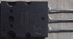
Your 2SC5200 looks just like what I have got . That measured out OK.
I think it should work.
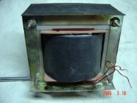
Your transformer looks cool. Is the secondary wire guage enough ? Can't say from the picture.
Cheers,
Ashok.
Your 2SC5200 looks just like what I have got . That measured out OK.
I think it should work.
Your transformer looks cool. Is the secondary wire guage enough ? Can't say from the picture.
Cheers,
Ashok.
rajeev,
I'm sure you have made transformers before and know all the rules, but the one in that pic doesn't seem to have any insulation between the bolts and the frame. Is the bolt head insulated on the other side?
I'm sure you have made transformers before and know all the rules, but the one in that pic doesn't seem to have any insulation between the bolts and the frame. Is the bolt head insulated on the other side?
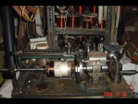
Rajeev,
can you tell a bit more of the hand winding machine ?
Please do not say you are going to diy electrolytics too !
impressive stuff,
jacco.
can you tell a bit more of the hand winding machine ?
Please do not say you are going to diy electrolytics too !
impressive stuff,
jacco.
- Status
- Not open for further replies.
- Home
- Amplifiers
- Solid State
- Favorite High Power Output Transistor