Ashok, the best painting for ready PCBs is following : buy in an " musician " shop resin for bow and in chemist's drugstore trichlorethylen. At first step wash soldered PCB by brush and trichlor. At second step dip the brush to trichlor and if is still damp, " paint " several times resin and in the end paint by this brush PCB. Result is " glass looked " painting, which is " immediately " hard and ( if you can ) easy solderable. This method is much more better than painting by " alcohol "method, but ! attention ! - trichlorethylen is little bit poison, so you must do it on " free air ", not in cloose room.
Hi Upupa Epops,
Yes that is an easy way to protect a soldered board. However I use a layer of clear acrylic paint . That is clear acrylic paint used for painting cars. You can also get them in a spray can at a much higher price. I wonder if it's the same as the acrylic conformal coating that also comes in cans at an even higher price !
A 100ml tin of acrylic paint ( clear acrylic lacquer) hardly costs anything over here. However soldering over it requires the coating to be scraped off in the area. It will burn off with the soldering iron but smells awfull and will leave some burnt residue in the area.
Cheers.
Acrylic paint is for nothing - as you say, by resoldering smell and burn. My method is better - after resoldering you can easy paint it by clear trichlor and all is the same as before 😎 . Try it and you will see 😉 .
Thanks to all for the support ,
Bill Fitzpatrick must be thinking who is this guy " from the stone age " ,
well when you see the pcbs of the same project by JensRasmussen , I
do feel embarrased to show my work , but I had already made it clear
and said eirlear in the post 239 "I am making the pcb layout on graph
paper and will plan a simple layout so that it can be handpainted on a
single sided board . All components and transistors will be
accomodated on a single board ." By this I ment that it is a truly DIY job
and I will be doing everything myself , I will make all at my workshop only
--- that is the pcb , chasis , and even the mains transformer . Like this
other than my satisfaction of making the amp I will be saving a lot of
money , these pcbs are costing me less than one USD , and the whole
amp 800w per channel at 4ohms and 1500w per channel at 2 ohms ,
with 11 pairs of output devices , 50,000 MFD caps per rail , and a heavy
duty transformer will cost me less than 200 USD , where if I remember
right Jens pcbs only cost 60USD . I wonder how many other people can
make this project in this cost . Here branded amps of similar specks ,
with lesser no of devices and caps cost not less than 1000USD , I have
also noticed that my amps which I have made eirlear run much cooler
than the branded amps and give very good punch , hence I am happy
with them for my sound system .
K-Amps
I am highly toughed by your support and see you as a very matured
person .
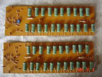
I have started mounting components on thr pcb pic in att
Bill Fitzpatrick must be thinking who is this guy " from the stone age " ,
well when you see the pcbs of the same project by JensRasmussen , I
do feel embarrased to show my work , but I had already made it clear
and said eirlear in the post 239 "I am making the pcb layout on graph
paper and will plan a simple layout so that it can be handpainted on a
single sided board . All components and transistors will be
accomodated on a single board ." By this I ment that it is a truly DIY job
and I will be doing everything myself , I will make all at my workshop only
--- that is the pcb , chasis , and even the mains transformer . Like this
other than my satisfaction of making the amp I will be saving a lot of
money , these pcbs are costing me less than one USD , and the whole
amp 800w per channel at 4ohms and 1500w per channel at 2 ohms ,
with 11 pairs of output devices , 50,000 MFD caps per rail , and a heavy
duty transformer will cost me less than 200 USD , where if I remember
right Jens pcbs only cost 60USD . I wonder how many other people can
make this project in this cost . Here branded amps of similar specks ,
with lesser no of devices and caps cost not less than 1000USD , I have
also noticed that my amps which I have made eirlear run much cooler
than the branded amps and give very good punch , hence I am happy
with them for my sound system .
K-Amps
I am highly toughed by your support and see you as a very matured
person .
I have started mounting components on thr pcb pic in att
Attachments
rajeev luthra said:Thanks to all for the support ,
K-Amps
I am highly toughed by your support and see you as a very matured
person .
I have started mounting components on thr pcb pic in att
Mr. Luthra, Thanks for your kind words, however I do not consider myself matured, just "experienced". 😀 It does wonders for one like me to step out of my midwest abode and visit different countries. It is estimated that 96% of people living in Indiana have not left the US ever, and 47% have not left the state..... In a highly global nation like the US, this stat is an eye opener.
We just don't respect or appreciate what other people live with outside our borders, we have it too good!😉
regards,
Hi K-Amps,
You can call me Rajeev , Mr Luthra is very formal ,
You are right , inspite of all the mediums like T.V. internet etc there is not
much exposure in many respects .
I have been making some sub horns for pro use , if you would like to see
pictures you can e-mail me , my id is systems_rajeev@rediffmail.com ,
I can send them in small size by e-mail .
There has been too much deley in my amp , now I have collected all the
components ( I was waiting for the 100v caps ) , I have wound the mains
transformer which will be compleate and tested soon .
With Best Wishes
Rajeev
Great work,
I love the size of the PCB 🙂

Regarding cost, there is a huge difference in what parts and labour cost in different parts of the world.
This has to be taken into the equation when comparing prices. My PCBs are manufactured in scandinavia, thus they suffer from expensive lobour hours and huge taxes (25%)
\Jens
I love the size of the PCB 🙂
Regarding cost, there is a huge difference in what parts and labour cost in different parts of the world.
This has to be taken into the equation when comparing prices. My PCBs are manufactured in scandinavia, thus they suffer from expensive lobour hours and huge taxes (25%)
\Jens
Hi Jens,
While labour costs are lower here , so is the finish - I think.
To get it done really well it costs much more. Maybe still cheaper than abroad. However we end up paying more money to get 'premium parts' if we want them. So it ends up being expensive . But standard caps and other parts are reasonably priced. So a direct comparison of price is not easy or accurate.
Rajeev,
Are you using large computer grade capacitors or using multiple small pcb mounting variety ? Someone mentioned that they prefer multiple small values to a single or double large value.
I just bought two 2SC5200 and one 2SA1302 from the local market.
The original 2SC3281 I have has a base collector cap of 1300pF. One 2SC5200 with similar type markings has 1020pF and the second 5200 with smooth printed area has 448pf. The 2SA1302 has 148pf. All from base to collector.
So I guess only the first 5200 is possibly genuine. The ones with lower capacitance also have leads that have a slightly different shape at the exit point from the plastic casing. The plastic casing near the leads is also notched . The original and good local part have a straight edge at the point where the leads come out.
cheers,
Ashok
rajeev luthra said:I have wound the mains transformer which will be compleate and tested soon .
Rajeev,
Will you be posting on the transformer ?
Place someone from the West a year in India, he'll be dead.
Bring someone from India to the US for a year, he'll be rich.
Regards,
J.
For amplifier up to 120W I like single pair of TIP35C/TIP36C by STM or KEC. Especially bass is rich with them. For the best 120W mid-high I prefer 2SA1303/2SC3284, those are ring-emitter transistors by Sanken.
For up to 200W I like single pair of KTA1943/KTC5200 (made by KEC under Japanese license I think - those are some cheaper and no worse).
Finally, the best single pair to me for 300W amplifier has been 2SA1216/2SC2922 by Sanken.
I agree with other guys that Sanken's products might be more popular and valuable as the datasheet parameters are fully-real-and-more. Here again their web-page, all datasheets there.
http://www.sanken-ele.co.jp/en/
To Alme : Sound of output transistors is nonsense. On sound of amp are signed different things, but sure they are related to the speed of these transistors. 😎
Pavel, to you it may be nonsense, but not more than hi-end cables. 😀
I have heard clear differences by merely subbing OP devices. Case inpoint, Subbed 2sd424/2sb554 with MJ15024/25, sound got restricted, harsh and fatiguing in a class-B amp.
Bias was set to similar for both, perhaps that may be a factor. The same is true when I subbed the 2sd424/2sb554 with 2sc5200/2sa1943.
The sound was softer, more detailed, the HF had sparkle without being edgy, the bass seemed extended and less punchy.
It has been my experience that transistors do sound different. Granted that they can be tweaked further perhaps to sound more similar. But the point just like every transistor has different gain, speed, current and voltage handling, why is it hard for you to think that perhaps they sound sound different. 😉
In second case is explanation easy : newest ones have much more higher beta, so VAS was less loaded, which cause lower distortion. You can't change for example low speed ones with high speed oned, what is common case of changing ( people change old type with modern one ), 'cos in most of cases is amp unstabil.
I agree, thats why I have found in most (not all) cases that changing with higher beta often makes he sound more listenable.
Well I didn't want to say that TIP35C/36C sound any worse than for example sanken's LAPTs; but most listeners notice there is a little difference. Yes that's maybe true stuff about beta, because mostly I have build twin darlington output follower not triple.
Anyway some manufacturers prefer TIP35/36 as output even for higher quality products. It seems that Rod Elliott also paid a tribute to them.
I like TIPs for their reliability especially - 25A current claim is real and allows to drive even 1 ohm load sometimes! - provided that they are mounted well with metal clip over.
Wow there is life in this thread again !!
Jens ,
Thanks for the encouragement ,
I did not mean to compare cost , what I meant was that , this is what I
could do in a minimum diy budget and tried to show how low my cost
was by doing ALL the work myself , although it is not the best , but at
least I get a lot of satisfaction of working on the project all by myself .
Also it is better to do it than not doing it at all .
Sometimes COST and non availibility of good gear encourage us to go
DIY .
I have a touring sound system and use only self made gear ( other than
the mixing consoles , digital processors , and microphones ) I even
make professional loudspeakers myself which are reasonabilly good (
again NOT the best ) I wonder if anyone uses DIY gear at the level I do , I
have a few pictures of the New Year Bash in which over 2000 people
danced at yeshwant club here ,
( if anyone wants to see the pictures , please send me an e-mail )
Ashok
You are scaring me . I had posted a picture of the output transistors that I
have , to me they look very original , what do you say ?
Regarding Caps , I am using small 100v caps on the pcb , the main filter
caps are 50v only , 100v screw type caps were availible but they were
very bulky and expensive , by using 50v caps the cost is even less than
half , I needed a 62v-0-62v transformer , but I made a transformer with
four 31v windings , I will use four bridge rectifiers & banks of 5x10,000
Mfd 50v caps after each rectifier , like this I will have four independant
supplies , then I will connect two of these in series for each rail and
ground the centre . Like this the caps will be in series but their Mfd will
still remain 50,000Mfd per rail . Please let me know if I am wrong here ?
.
Jacco vermeullen ,
I will post the picture of the transformer soon , it is not a toride but an old
type with E I laminations . The advantage of making my own transformer
other than lower cost is that I can make one of any voltage / VA rating as
per my requirement , that too when ever I want one .
With best wishes
Rajeev
Hi Rajeev,
I am trying to make a small hfe tester for power transistors. You will need a DMM to measure the hfe.
I think the hfe and capacitance measurements will be enough to let you know if the devices are genuine or not.
Like - high hfe ( say over 200 ) and low capacitance from base to collector ( 200 pf or so ) probably indicates a fake device.
But I have several good devices and will measure them all and see what kind of spread there is between devices.
Will post info on a new thread when the tester is ready and if it works ! I've no time now, but I'll have a look at the pic you posted later on.
Cheers,
Ashok.
Rajeev,
2 banks of 50,000uF @ 50v in series gives you 1 bank of 25000uF @100v per rail ..... unless I misunderstood your arrangement
2 banks of 50,000uF @ 50v in series gives you 1 bank of 25000uF @100v per rail ..... unless I misunderstood your arrangement
K-Amps ,
Yes Two banks of 50,000Mfd 50v will be 25000Mfd 100v in series , BUT if you have seperate windings & bridge rectifiers they will be 50,000Mfd per rail , as two seperate DC supplies are connected in series , draw the diagram on paper , think and let me know , I am not an engineer but I think this is right , comment ?
Yes Two banks of 50,000Mfd 50v will be 25000Mfd 100v in series , BUT if you have seperate windings & bridge rectifiers they will be 50,000Mfd per rail , as two seperate DC supplies are connected in series , draw the diagram on paper , think and let me know , I am not an engineer but I think this is right , comment ?
- Status
- Not open for further replies.
- Home
- Amplifiers
- Solid State
- Favorite High Power Output Transistor