Hello!
Thanks for comment!
I have changed IC401, at the beginning of the repair.The new one is original, from Renesas Electronics.
The oscilloscope tips are placed at the junction point of the emitter resistors on the output transistors.
Hi Cosmin!
You post at the same time, sorry!
I was very surprised to see your picture!
The truth is that I would swear that I checked it, but what I'm sure of is that the transistor is set respecting the PCB screen printing.
I have the amplifier at work, tomorrow I'll check it again early
Thank you!
I just checked some pictures on the web, i´m almost sure that mine is reversed!!!
Regards!
Felix
Last edited:
Hello!
Well, I don't know how to say this ... I don't understand how I could make this rookie mistake.I feel ashamed and angry at myself.
It has been putting the transistors in the correct position and everything works as it should.The base voltage of the drivers are correct, and the bias adjustment is perfect. Even the distortion of the left channel has disappeared, no idea ....
I don't know how to thank you, Cosmin, and equally to everyone who has participated.
Your photo has given me ideas on how to update and improve the ampli.I just placed the multiturn order, and I plan to replace Q501-Q504 with MJE340 / MJE350 with heatsinks.
What is Q405, Q406 in your amplifier?
I also like how you put the bias transistors over the output ones.
Once again, thank you very much.
Best regards,
Felix
In my opinion do not replace working original semiconductors.
You can never buy the quality that the manufacturer received.
You can never buy the quality that the manufacturer received.
Hi As_Audio!
You're right, I may not be able to buy current components of the same quality as those used by Technics 30 years ago.
But if I tell you that I have a large number of old and original components?
The fact is that I have been recovering obsolete equipment components for many years, power stages to which only one channel worked, old mixing tables and things like that.
And in some cases, for example on Ebay you can buy NOS (new old stock) components.
What I have noticed is that some components of the amplifier get quite hot, and I have thought about replacing them with more "robust" ones.
But if you tell me what better not, then I leave it as is, now that it works.
Thanks for answering
regards
Felix
Thanks As_Audio for your comment, I think I can learn something from all people🙂
I better leave it as it is. I will only change the trimpot and add some heatsink to the TO92.
Thanks!
I better leave it as it is. I will only change the trimpot and add some heatsink to the TO92.
Thanks!
Hello,
First, I'm glad everything is OK now - printscreen for those transistors is easily misleading (maybe should have been compared to Q417 - 420).
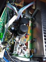
Second, the amp I rebuilt is an electric hazard. Starting from pcb (3oz), everything is 'over wheighted'. Any producer used/use fusible resistors here and there. Except for those double emitor resistors (their design), mine are all metal film and none bellow 0.4W. All are increased in wattage. Even poor diodes are 0.5W (Zeners, too). I have a problem with heat inside electronics and that's why one will notice the abundance or heatsinks although there's no need for some of them. Former ceramic capacitors became plastic and here/there some C0G. Those between GND and chassis are left in place. All components paired as much as possible (even within same lot). Etc, etc...
What I obtained? An amplifier that, in my opinion, ...just amplify! With no issues at all! This is the reason I don't use her anymore - depending on the CD's mastering, I had to change players to enjoy music. At some point, I used 3, each with analog/SPDIF outputs plus the digital/analog inputs of the amp. To many combinations to make for an audition of 1-2 hours.
To answer your question, Felix, for Q405, 406 I used Toshiba's 2SA1360. I'd agree with Mr. @as_audio if Panasonic/Matsushita would've use in this case 2SA1124 available at the time and produced by themselves! And 2SC2632...
Super-diode transistors are kept in place by sheets of brass.
Well, I think this is a kind of closure of another succesfull restoration of an integrated amplifier with - in my opinion - interesting design and performance.
Best wishes everybody,
Cosmin
First, I'm glad everything is OK now - printscreen for those transistors is easily misleading (maybe should have been compared to Q417 - 420).
Second, the amp I rebuilt is an electric hazard. Starting from pcb (3oz), everything is 'over wheighted'. Any producer used/use fusible resistors here and there. Except for those double emitor resistors (their design), mine are all metal film and none bellow 0.4W. All are increased in wattage. Even poor diodes are 0.5W (Zeners, too). I have a problem with heat inside electronics and that's why one will notice the abundance or heatsinks although there's no need for some of them. Former ceramic capacitors became plastic and here/there some C0G. Those between GND and chassis are left in place. All components paired as much as possible (even within same lot). Etc, etc...
What I obtained? An amplifier that, in my opinion, ...just amplify! With no issues at all! This is the reason I don't use her anymore - depending on the CD's mastering, I had to change players to enjoy music. At some point, I used 3, each with analog/SPDIF outputs plus the digital/analog inputs of the amp. To many combinations to make for an audition of 1-2 hours.
To answer your question, Felix, for Q405, 406 I used Toshiba's 2SA1360. I'd agree with Mr. @as_audio if Panasonic/Matsushita would've use in this case 2SA1124 available at the time and produced by themselves! And 2SC2632...
Super-diode transistors are kept in place by sheets of brass.
Well, I think this is a kind of closure of another succesfull restoration of an integrated amplifier with - in my opinion - interesting design and performance.
Best wishes everybody,
Cosmin
Dears, I'm attempting to repair my loved SU-V90D amp. I have to substitute the final stage transistor. What do you suggest to use instead of the Toshiba 2SA1302 / 2CS3281 with something equivalent in current production? I would't like to go on the used market or incur on fakes ones.
Thanks
Thanks
Last edited:
Hello,
Toshiba gives as equivalent the Onsemi's 2SA1943/2SC5200. The American datasheets of these mention them as FJL4215/FJL4315. Mouser - the only place I Iooked for - has one of them in stock, the other available at the end of January.
Regards,
Cosmin
Toshiba gives as equivalent the Onsemi's 2SA1943/2SC5200. The American datasheets of these mention them as FJL4215/FJL4315. Mouser - the only place I Iooked for - has one of them in stock, the other available at the end of January.
Regards,
Cosmin
Hello!
Cosmin! I'm glad to read you, I hope you and your family are well.
Thanks to you, my SU-V90D is still here.
Icos1, If you change your mind and want an original used pair, send me a private one. I'll give them to you, but depending on where you are, we would have to talk about shipping.
Of course, I have no lucrative interest in this.
Greetings!
Felix
Thanks so much Felix, I appreciate. I'm based in Italy, I'm sending you a private msg.Hello!
Cosmin! I'm glad to read you, I hope you and your family are well.
Thanks to you, my SU-V90D is still here.
Icos1, If you change your mind and want an original used pair, send me a private one. I'll give them to you, but depending on where you are, we would have to talk about shipping.
Of course, I have no lucrative interest in this.
Greetings!
Felix
Thanks Iomis, I appreciate. I saw that you have managed to rebuilt the PCB in a better quality material from previous post. DO you have the master file to reproduce the PCB also for future preservation? ThanksHello,
Toshiba gives as equivalent the Onsemi's 2SA1943/2SC5200. The American datasheets of these mention them as FJL4215/FJL4315. Mouser - the only place I Iooked for - has one of them in stock, the other available at the end of January.
Regards,
Cosmin
Hello!
Felix, I'm smiling thinking of our successfully ended "struggle" and I'm happy to see you're well!
Icos1, if you send me a PM with your email I'll give you the pdf file. However, I must warn you that - although functional - is not a beauty and, if you ever decide to produce it, there's a point on it where I didn't like the behavior under voltage (+ & - rails too close). My skills as CAD user are of a beginner and took me many months to make it. I remember loosing patience a few times. Therefore, I recommend the pdf as a starting point and not as final version. I'm not mentioning the price for a 147mm x 248mm pcb. Mine was fairly cheaply made - limited production options - but the base material was fine.
Best regards, Happy Holiday,
Cosmin
- Home
- Amplifiers
- Solid State
- Faulty Technics SU-V90D