Hi everyone!
This is my first post, but I read the Forum for years.
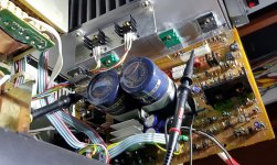
I have been given a Technics SU-V90D in an unfortunate state, completely disassembled and with a handful of components in a bag.
It has taken me a long time to start it up, it had a large number of broken active components, not only in the power stage, but also in the previous one, input selectors and even in the LED controllers.
After all these problems that have arisen in the repair, the ampli turns on perfectly, closes the protection relay and sounds really great with headphones, but with 8 ohm speakers a strong distortion appears.
There are no short circuits, no noises and nothing heats beyond normal.
In no case is there continuous current at the output.
The problem I think is coming because I can't adjust the bias of the AB class exit stage. According to the manual, there should be + 1v and -1v in the driver bases. I have 2,8v at the base of the positive driver and 1v at the base of the negative driver.
Now the weirdest thing is coming: this happens with the standard operational, the M5219P. If I put another, like the NE5532, then I have -2,8v at the base of the negative Driver, and -1v at the base of the positive. With another quality opamp, the JRC2043D the voltage goes to 3,2v and 1,4.
I just tried an NEC 4570 and the same, 2,8v and 1v, both positive. I clarify that I have the operational ones with sockets, I don't know if it influences anything.
The voltages in the opamp IC 501 are correct except those mentioned, and correct are in the pair of output transistors.
I have reviewed, checked or replaced all the components of the bias circuit of a channel, since this happens in both channels at the same time, which puzzles me even more, since apart from the opamp IC401 they are two separate stages, and all the chip voltages are correct.
I have verified that the bias adjustment accentuates the problem, so I have it to a minimum.
All the semiconductors I use are 100% original, bought by ebay in Japan, Germany and the USA.
I read that this Technics technology consists of a class A amplifier followed by a power stage in class AB. I explain myself fatal, but I have read some documents on the internet to understand the operation of the amplifier.
As far as I understand, the class A part is working perfectly, as I say, with headphones it sounds spectacular.
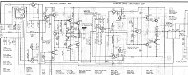
If you look at the scheme attached, the voltage amplifier goes to the output through a resistance of 1 Ohm.
I put the service manual in 3 RAR, is almost 10MB.
I have analog and digital scope, multimeter, audio generator and all habitual stuff.
Thank you for reading. Any input is welcome.
Regards!!!
This is my first post, but I read the Forum for years.
I have been given a Technics SU-V90D in an unfortunate state, completely disassembled and with a handful of components in a bag.
It has taken me a long time to start it up, it had a large number of broken active components, not only in the power stage, but also in the previous one, input selectors and even in the LED controllers.
After all these problems that have arisen in the repair, the ampli turns on perfectly, closes the protection relay and sounds really great with headphones, but with 8 ohm speakers a strong distortion appears.
There are no short circuits, no noises and nothing heats beyond normal.
In no case is there continuous current at the output.
The problem I think is coming because I can't adjust the bias of the AB class exit stage. According to the manual, there should be + 1v and -1v in the driver bases. I have 2,8v at the base of the positive driver and 1v at the base of the negative driver.
Now the weirdest thing is coming: this happens with the standard operational, the M5219P. If I put another, like the NE5532, then I have -2,8v at the base of the negative Driver, and -1v at the base of the positive. With another quality opamp, the JRC2043D the voltage goes to 3,2v and 1,4.
I just tried an NEC 4570 and the same, 2,8v and 1v, both positive. I clarify that I have the operational ones with sockets, I don't know if it influences anything.
The voltages in the opamp IC 501 are correct except those mentioned, and correct are in the pair of output transistors.
I have reviewed, checked or replaced all the components of the bias circuit of a channel, since this happens in both channels at the same time, which puzzles me even more, since apart from the opamp IC401 they are two separate stages, and all the chip voltages are correct.
I have verified that the bias adjustment accentuates the problem, so I have it to a minimum.
All the semiconductors I use are 100% original, bought by ebay in Japan, Germany and the USA.
I read that this Technics technology consists of a class A amplifier followed by a power stage in class AB. I explain myself fatal, but I have read some documents on the internet to understand the operation of the amplifier.
As far as I understand, the class A part is working perfectly, as I say, with headphones it sounds spectacular.
If you look at the scheme attached, the voltage amplifier goes to the output through a resistance of 1 Ohm.
I put the service manual in 3 RAR, is almost 10MB.
I have analog and digital scope, multimeter, audio generator and all habitual stuff.
Thank you for reading. Any input is welcome.
Regards!!!
Hi! Thanks, but in Hifiengine it is:
Technics SU-V90D - Manual - Digital Integrated Amplifier - HiFi Engine
Regards!
Technics SU-V90D - Manual - Digital Integrated Amplifier - HiFi Engine
Regards!
Hello,
If I recall corectly, there are some mistakes in schematics (at least one electrolytic reversed). Use the silk screen to check if components are well installed. If you used 2SC1815 as VBE multipliers, make sure they have the same hFE rank as the originals.
Unrelated, relocate somehow Q303, 304 so you can add heatsinks. You might consider increased wattage for R619, 620. If you have the UK version, choose the right voltage for trafo's primary winding.
Regards,
Cosmin
Last edited:
Hi!
Iomis: I´m used new 2SC1815, original Philips, i supose the HFE must be near the originals.
Q303 and Q304 are now in a medium heatsink, screwed to the main heatsink, but thanks for the data. R619,620 are the originals, i will change for more wattage. I think that you know this particular amplifier, right?
Ilwhtt: Now i have the stock IC on IC501, M5219P, and the voltaje rails are corrects, but a very little down, because the zeners i use on rails regulators, 7v9 instead of 8v2. the voltaje on IC was +-7,2v.
Thanks a lot for the help
Regards
Félix
Hello!
As far as I know, Philips never made transistors using that code. Is specific to Japanese producers of those (and earlier) years. So you should re-consider your sources for semiconductors. If memory serves, I tried some BD series as VBE multiplier (considering better heat transfer to a TO-126 capsule) but it didn't work, so I ended using the initial C1815s (made by Toshiba). Now I'm convinced I didn't search enough but the amp is not in use so...
It seems to me that you're very close to solve the issue.
Best regards,
Cosmin
Hello!
Iomis: You're right, I don't know where I got the Philips thing.
The C1815s are from CentralSemiconductor, original, and with HFE completely within that mark the datasheet.
In fact, I have two variants and both are within the parameters.
I also think that it is very close, and by far, this is the amplifier that is costing me the most to repair.
But there is a lot of work behind.
I am convinced that there is little left.
Thanks for comment.
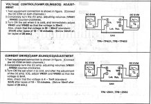
Douglas Blake: . Hello! I have completed the first setting of the Voltage Amplifier. All good up there, I think. The second is impossible. I have a lot of imbalance between the driver bases and it worsens when adjusting the Bias.
The fact is that with headphones it sounds perfect, clearly beyond half the volume. As soon as I connect the speakers, a strong distortion appears even at very low volume. I will try to make a capture with the oscilloscope.
Thank you very much for your interest.
Regards,
Félix
Iomis: You're right, I don't know where I got the Philips thing.
The C1815s are from CentralSemiconductor, original, and with HFE completely within that mark the datasheet.
In fact, I have two variants and both are within the parameters.
I also think that it is very close, and by far, this is the amplifier that is costing me the most to repair.
But there is a lot of work behind.
I am convinced that there is little left.
Thanks for comment.
Douglas Blake: . Hello! I have completed the first setting of the Voltage Amplifier. All good up there, I think. The second is impossible. I have a lot of imbalance between the driver bases and it worsens when adjusting the Bias.
The fact is that with headphones it sounds perfect, clearly beyond half the volume. As soon as I connect the speakers, a strong distortion appears even at very low volume. I will try to make a capture with the oscilloscope.
Thank you very much for your interest.
Regards,
Félix
Hello, Felix,
Distorsions on low volume make me think that polarization voltages of power transistors are too low. Check again components around VBE multipliers. Thermistors... those pots... even emitor resistors... R557, 558... Problem is on both channels and I'm guessing you used new ones and maybe misread some values. VBE of power transistors must be around 550 mV with no load and input shorted to ground.
Regards,
Cosmin
Last edited:
Hello!
In the bases of the power transistors there is + 0.4v, in the two rails. I should have + 0.5v and -0.5v, I know. But this comes from behind, from the VBE multiplier.
In the base of Q551 there are 1.41v, in the collector 2.8v and in emitter 1v. I have the setting to the minimum, because turning it increases the voltage on both bases.
On the IC 501 power rails I have + 7.7v and -7.1v. I am waiting for a batch of 20 8.2v zeners, I will pair two to see if I match these voltages more.
Appart of these, all the voltajes on the amplifier are more or less corrects. In any time there is DC on outputs.
After reading your post, I have rechecked each component of the Bias setting circuit. Everything is OK.
I have replaced the C1815 with new ones, although from the same lot. Same result.
Any possible substitute for the C1815?
At this time I have also noticed excess heat in Q402 and Q406, at the input of the voltage amplifier. I would swear it was not so before.
On the other hand, at no time have I kept the amplifier on for more than a few minutes.
What puzzles me the most is the fact that with headphones it works perfectly with music even at high volume. With a load of 8 ohms at a very low volume is all distortion.
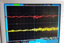
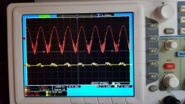
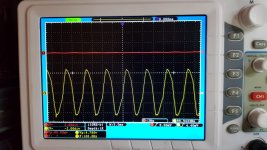
Attached Photos of the output signals, both channels, with 1khz sine signal, approx 1/4 of the volume with headphones.
The second photo is the same signal, at 1/6 of the volume, with an 8 ohm load. The distortion is horrible. I dare not turn up the volume
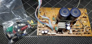
Other is the amplifier right now.
Thank you for reading!
Best regards,
Félix
In the bases of the power transistors there is + 0.4v, in the two rails. I should have + 0.5v and -0.5v, I know. But this comes from behind, from the VBE multiplier.
In the base of Q551 there are 1.41v, in the collector 2.8v and in emitter 1v. I have the setting to the minimum, because turning it increases the voltage on both bases.
On the IC 501 power rails I have + 7.7v and -7.1v. I am waiting for a batch of 20 8.2v zeners, I will pair two to see if I match these voltages more.
Appart of these, all the voltajes on the amplifier are more or less corrects. In any time there is DC on outputs.
After reading your post, I have rechecked each component of the Bias setting circuit. Everything is OK.
I have replaced the C1815 with new ones, although from the same lot. Same result.
Any possible substitute for the C1815?
At this time I have also noticed excess heat in Q402 and Q406, at the input of the voltage amplifier. I would swear it was not so before.
On the other hand, at no time have I kept the amplifier on for more than a few minutes.
What puzzles me the most is the fact that with headphones it works perfectly with music even at high volume. With a load of 8 ohms at a very low volume is all distortion.
Attached Photos of the output signals, both channels, with 1khz sine signal, approx 1/4 of the volume with headphones.
The second photo is the same signal, at 1/6 of the volume, with an 8 ohm load. The distortion is horrible. I dare not turn up the volume
Other is the amplifier right now.
Thank you for reading!
Best regards,
Félix
Attachments

Hello, Felix,
Any news? I don't know what else to suggest... Voltages around other multipliers (Q421, 422) are ok? If necessary, I'll open mine for some comparisons and tell you what transistors I used in different locations (a lot of unavailable now TO-126s), A1943/C5200, A1837/C4793 etc. I remember committing sacrilege and used in this Japanese amp Fairchild's BDs for Q451, 453🙂 - not wrong, but somehow strange. Anyway, I don't think there's any A1123/C2631 left in. I also remember trying to use Panasonic products as much as possible - managed to buy last T-HA 15000uF/80V electrolytics from Mou*er.
Honestly, I have my doubts about *Bay sources for semiconductors, better search for modern substitutes available in stocks of big retailers.
Here's a source for TO-92 heatsinks. Or these.
Also you can follow the signal with oscilloscope through the amp to see where is starting to be ''corupted'', although seems final stages.
Best regards,
Cosmin
Last edited:
Hello!
First, thanks for answering. Second, sorry for the delay in answering you.
A lot of work this week and a little boy who demands a lot of attention ... so my time for electronics is very, very limited, for now …
The voltages in Q421, 422 are correct, although the transistors work hot, approx. 50 ° C. I accept suggestions for substitutes.
You are very kind to offer to open your amplifier, thank you, but I hope it is not necessary.
Apart from online stores, I have access to a huge amount of original, although used, components from discarded circuit boards, power stages and other HIFI amplifiers.
My first idea, when I started repairing this amplifier was to leave it as original as possible. Right now, all I want is for it to work, and work well. I plan to use it in my modest Home Studio.
In the first start-up I had MJE340 / 350 in Q501-Q504. When I found the imbalance in the driver bases, I replaced them with the "originals" C2631 and A1123, with the same result.
I have ordered some uPC4570 from NEC, to discard IC401.
Thanks again!
Regards!
Felix
Hi,
As VBE multiplier are commonly used BD135, 137, 139. Or MJEs. Almost any NPN. If you used 2SC1815 for Q421, 422 make sure they have good contact on heatsinks. That stages are biased in class A and is normal to be hot. Anyway, it seems to work fine (that 1st amplifiers) and you have 0 V on both pins 2 at TP401, 402.
I'm looking at your pictures... Later, I'd go for 500 Ohms multi-turn pots as VRs. And from which point you took GND for measures ?
Regards to you and your family,
Cosmin
Hi Cosmin!
Thanks for answering!
I have ordered a BD139 from a trusted store. Today the zener have arrived, as soon as I have everything I will continue with the tests.
The mass reference is taken from the common point of the main capacitors. In this amplifier the chassis is not mass, but is decoupled from it through a pair of ceramic capacitors.
I sign the idea of multiturn pots for when it works .....
The voltages in Q421 and Q422 are correct, but those are not the ones that get hot, I was wrong, sorry, they are Q401-Q405 and Q402-Q406.
More curious things: The right channel "works" to some extent, where it cuts the signal. The left distort immediately, and when that happens, the distortion seems to happen to the right channel as well. This with 8 Ohm speakers. With 32 Ohm headphones it works perfect at any volume.
When you put the tip of the oscilloscope to follow the signal on Q401-Q405, it introduces another distortion. I have to look at this more closely.
Thank you very much for still being there. I've been with this amplifier for too long now, and sometimes it makes me want to give up, but I come back again.
Greetings And thanks again!
Felix
Hi,
Re-check cables, connections from main pcb to speaker selector/headphones pcb and speakers connectors pcb. And between these two. Make sure you soldered well (those thick) cables on points 501, 502, also check conectors J19, 20 and their pairs. Also, take a closer look to speaker selector switches...
It seems your version is not multi-voltage and main input is for 220V, so you should expect increased voltage here-there or voltage drop on some components (I'm assuming you're on 240V AC).
C603 is wrong showed (reversed) in schematics, but - if I remember well - correct on silkscreen.
Also - althought difficult - is necessary to keep main pcb conected to J14 and/or J18 while injecting signal via CD DIRECT and have POWER AMP DIRECT and ANALOG selected on front panel. There's something about ground rail (signal) that goes around the entire amp from pcb to pcb... If one is out of this 'loop' (except DAC stage), you'll loose (signal) ground. Maybe a cable broke between so many pcb's... Inject signal directly on pins 1-2 and 6-5 of J14.
Best regards,
Cosmin
Hi Cosmin; I'm glad to read you!
I have carefully followed your instructions, unfortunately, without changes in the performance of the amplifier.
At the moment I have two problems, one is the strong distortion with loudspeakers, more in the left channel, of which I do not find the origin, and another is the imbalance in the polarization voltages of the drivers.
I don't know if they are related.
All amplifier voltages are more or less correct, except those of the output bias circuit on both channels.
I replaced the C1815 with a BD139 on the L channel, without changes.
Different voltages and do not vary with the trimpot.
At the base of Q553, Q554 there are 2.8v where it should have approx 1v, while at the base of Q555, Q556 there is 1v positive, where it should be negative.
I have ordered new A1535 and C3944, I have measured them and according to the datasheet they are perfect.
I've checked everything again, I don't know how many times ...
At this point, I feel a little tired and unmotivated ...
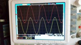
Attached some photos, in one you can see the amplifier working without load, with an output voltage of about 30vpp.
With music it's the same, it works perfect with headphones, but not with speaker load.
.
Best regards,
Félix
At the base of Q553, Q554 there are 2.8v where it should have approx 1v, while at the base of Q555, Q556 there is 1v positive, where it should be negative.
I have ordered new A1535 and C3944, I have measured them and according to the datasheet they are perfect.
I've checked everything again, I don't know how many times ...
At this point, I feel a little tired and unmotivated ...
Attached some photos, in one you can see the amplifier working without load, with an output voltage of about 30vpp.
With music it's the same, it works perfect with headphones, but not with speaker load.
.
Thanks for staying there
,
Best regards,
Félix
Attachments

- Home
- Amplifiers
- Solid State
- Faulty Technics SU-V90D