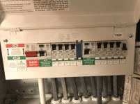
The consumer unit [CU] is the box that takes in the connection from the mains incoming (mine goes to a splitter and one side goes to the house CU and the other a hifi CU) this contains the MCB circuits and the RCDs.
For my Hifi I have a 2way (2xRCD) with 4 MCBs of each, that gives me 8 connections each at 16A. I take each on 30A cable to a single socket. Each socket has an earth back to the CU.
My safety earth is separate to the signal GND, safety earth is on each plug star-connected to the consumer unit.
Signal GND is connected by equal length low impedance cables that all join a single socket to then join the CU
All components are plugged into one of the 8 sockets, and as earlier each has it's own spur into the CU
Attachments
Thanks, I'm beginning to understand the installation. You have a number of wall outlets with individual pulls to panel (the CU), and an elaborate flying system signal ground also pulled back (separate from power PE) to panel and safety Earthed there?
What can I tell you, except Don't do that. You're creating a ton of PE ground loops and generating significant (noise) voltage differences between signal ground and chassis/PE grounds, and each somewhat different at each end of interconnecting cables. This is the opposite of what you want. You want to be a bird on a wire, with a single connection from your local PE back to panel (CU).
All audio electronics should be plugged into one power distribution strip, and it should be the only connection to mains, plugged into a single wall outlet. No other connection back to panel (CU). If you wish to explore safe-ish options to separate chassis/PE from signal ground, you might research the 10R // big diode bridge method. It provides 10R of isolation below peak differences less than about 1.4 VDC +/- .
All good fortune,
Chris

Thanks Chris,
Chassis safety Earth and Signal GND are NOT joined anywhere except at the GND in the CU. The units are still all safe and compliant in this respect.
Each signal GND is joined with equal impedance cables at one plug socket, and then joins the CU.
I understand the logic and convenience of 1 power strip to prevent GND loops, but it also compromises from my experience the sound in comparison to the individual socket approach, I also interestingly found the separation of the Signal GND to Chassis ground improved things.
My pre amp has 2 GND (signal and chassis) terminals with an optional to remove jumper, and my power amp had a lifted GND with 100R originally, my DAC was ungrounded, and my turntable takes GND from the pre amp.
Finally taking the GND from the DAC DOES create a small GND Loop, and on full volume you can hear this, but not anywhere near any system volume I use even if I create deafening levels.
However it DOES sound better! so I leave it that way
Rich