Yes, I've got two different TK2050 and they both get warm - one is TC2000 and the other is TC2001. I'm not sure what the mosfet stages are from memory but STA505 seems likely. They don't like air core coils either - the coils warm up noticeably (about 40-45C) but not as much as the TPA3116 (70C).
I've tested all six TDA8932 amps - found two soldering errors. If the bootstrap pins/parts or input pins/parts aren't soldered well, the amp has a kind of gurgling distortion of varying levels. It's very audibly different between a good solder join and a poor one.
Since the parts I bought all work well, here's where I bought them
TDA8932 Chips Y6.80 each ??????D?????? TDA8932BT TDA8932 ??-???
"iron silicon aluminium" toroid inductors 50125A 13MM????? 15UH 1.0? 10A ??????? ????-???
PPS film caps and other parts 1210 ?????? 1UF 105M 16V ?????? ECPU1C105MA5-???
Last edited:
I've built up all six of Matt's boards in various configs. I've listened to three so far - two are identical config and sound identical so it seems the builds are fine.
Awesome! Glad the postal service found them, and delighted to see them built up and playing music for you (you work fast!). Don't forget on the v1.0 (smaller) boards, the headers are mislabeled:
Board reads: SLAVE|GND|SLP|GND|MUT|GND|POS|GND|NEG
Should be: SLP|GND|MUT|GND|SLAVE|GND|POS|GND|NEG
The signal inputs are OK, but the slave, sleep, and ground labels are incorrect.
Regarding the TK2050: many, many years ago, I had a HiFiMeDIY T2, which is based on the TK2050 platform. I had to look at my sales invoice, looks like that was back in 2012. I think that may have been the first "DIY" amp I built ("DIY" in quotes because I got a completed board, just had to wire up input, speakers and power). At any rate: what really got me into DIY was the $10 Sure tpa3110. I remember thinking it sounded noticeably better than the T2. But don't put too much stock in that comment, though: I hadn't developed any critical listening skills then, pretty sure I didn't have a discreet DAC (likely line level analog out from my computer), and can't even remember what speakers I was using. But playing with that tpa3110 board started a multi-year long love affair with the tpa311x amps, modding them, etc, and ultimately leading me to designing my first PCB.
But I don't want/need these powerful beasts. To drive my MarkAudio A7.3 speakers I just want a low/mid power amp, and the one I'm about to build is the TPA3250 EVM board.
In what enclosures are your A7.3 speakers?
I have two tpa3251 amps, the TI EVM board, and the 3e-audio. They are way more power than I need, but they do sound good. I have a few amps I'm happy with now: my tda8932, the tpa3251s, and an LM3886 amp. Shuffling between them with my different tda1387 DACs.
Medium trapezoidal miniOnken (dMar-Ken7.3mT). Dave Dlugos first mentioned this model in 2015 -In what enclosures are your A7.3 speakers?
http://www.diyaudio.com/forums/planet-10-hifi/186350-planet10-hifi-minionken-plan-set-subscriptions-4.html#post4516844
Fast but careless! Thankfully fault finding was quick too.Awesome! Glad the postal service found them, and delighted to see them built up and playing music for you (you work fast!). Don't forget on the v1.0 (smaller) boards, the headers are mislabeled:
Board reads: SLAVE|GND|SLP|GND|MUT|GND|POS|GND|NEG
Should be: SLP|GND|MUT|GND|SLAVE|GND|POS|GND|NEG
The signal inputs are OK, but the slave, sleep, and ground labels are incorrect.
Noted the mislabelling - no problem at all - and thanks again for the boards - very generous of you 🙂
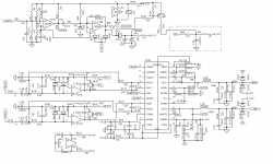
I want to disclose here one my trick with TDA8954 which is pretty much the same thing as TDA8932 but more powerful. Why did I add that integrator into the FB loop? TDA8954 5-8 years ago was a quite attractive and inexpensive IC, however, it had S/N and TDH inconsistent from sample to sample. Extra integrator reduced THD@1kHz for about 5 times, and accordingly S/N, hence MP became pretty seamless. Also was reduced the disturbances from one IC to another if running together and close to each other.
Attachments
I want to disclose here one my trick with TDA8954 which is pretty much the same thing as TDA8932 but more powerful. Why did I add that integrator into the FB loop? TDA8954 5-8 years ago was a quite attractive and inexpensive IC, however, it had S/N and TDH inconsistent from sample to sample. Extra integrator reduced THD@1kHz for about 5 times, and accordingly S/N, hence MP became pretty seamless. Also was reduced the disturbances from one IC to another if running together and close to each other.
Good to see someone working outside of the datasheet reference circuit. Do the integrating buffer/control amplifiers still leave an overall constant gain in the audio band? Is C136/R133 a Zobel network? SPK4 is connected to OUT4 such that you have nested feedback?
The first "composite" amplifier design I have seen with a class D power stage. Very interesting.
Do you recall the absolute THD figures you obtained?
You are probably aware of TDA8954 in a 23pin DIL/SIL package for "through hole" mounting which still makes it very interesting for DIY.
Well done,
FauxFrench, I see no reason to not go for SMD if I have an option SMD/TH, whatever DIY or MP. Exact THD+N I can't call for now, probably .015-.025%@-3db@1kHz for single IC on dedicated PCB(THD=1% power is about 110W). 1-10W it was less or within .01%. TL072 was chosen as the cost-effective candidate, and for the best performance, I recommend to use something better yet. Of course closed loop gain is linear enough in 20-20000Hz(usually customers asked +/-.5db, and some +/-1db). The input BW was limited by DSP preamp, if you gonna use bare amp, better add there LPF and buffers. BTW, I didn't notice any sound improvement, I just made my customers confident regarding formal specs. It seems 8954 has a very light amount of loop gain if external FB loop is possible and stable. I believe 8932 is the same, and my mod is implementable as well.
Seems to me that TDA8954 is double trouble for getting the best SQ because its designed for balanced power supplies. So both VSSA and VDDA need attention. TDA8932 has the advantage of running on a single rail.
From a brief look at the DS, the VSSA rail is 5dB more sensitive to PSU noise than VDDA. Decoupling components on each rail in the application though are the same. Compared to TDA8932 though there's 220nF rather than 100nF on those pins.
FauxFrench, I see no reason to not go for SMD if I have an option SMD/TH, whatever DIY or MP. Exact THD+N I can't call for now, probably .015-.025%@-3db@1kHz for single IC on dedicated PCB(THD=1% power is about 110W). 1-10W it was less or within .01%. TL072 was chosen as the cost-effective candidate, and for the best performance, I recommend to use something better yet. Of course closed loop gain is linear enough in 20-20000Hz(usually customers asked +/-.5db, and some +/-1db). The input BW was limited by DSP preamp, if you gonna use bare amp, better add there LPF and buffers. BTW, I didn't notice any sound improvement, I just made my customers confident regarding formal specs. It seems 8954 has a very light amount of loop gain if external FB loop is possible and stable. I believe 8932 is the same, and my mod is implementable as well.
Many thanks for the elaboration. I will try it out one day when I have time. TDA8954 can be bridged (single supply) to a power level where cooling may be difficult. The advantage of "through hole" components is if you do bread-board work using Vero-boards. For you as a professional that is most likely not the case.
I think no one Pro without DIY stage 😉 I was a DIYer which was so impressed by another Pro(Bruno Putzeys), that I decided to improve myself.
Hi guys. Have read through a lot of this thread but I am lost on some of it. I am a diy audio beginner!
I have just received 2 boards and they have the 'T' chip. What is the difference between this and the B or BT chips?
And can someone explain simply or a little schematic of the diode thing to power two boards from one psu? Or can I just go ahead and do it without diode?
And what is the best way to feed a stereo signal to the 2 boards?
Thanks
James
The only difference I've noticed (from reading and re-reading the DSs a few times) is the T version (absent B) needs two extra 1Mohm resistors across the bootstrap caps.
To feed a stereo source to two boards the best way you'd want to turn one of the boards into differential input. Then its -ve input terminal connects to the ground on the first board. Don't bring the ground (shield) of the signal onto both boards or you'll end up with a ground loop.
To feed a stereo source to two boards the best way you'd want to turn one of the boards into differential input. Then its -ve input terminal connects to the ground on the first board. Don't bring the ground (shield) of the signal onto both boards or you'll end up with a ground loop.
I assume it is the small blue boards you have received.
I managed to find the datasheet for the TDA8932T. It seems identical to all what is now sold as TDA8932BT in the SO32 housing. You may do a thorough comparison if you can find an important difference: TDA8932T IC CLASS-D POWER AMP 32-SOIC NXP Semiconductors datasheet pdf data sheet FREE from datasheetz.com
I do not understand what you mean by the "diode thing". From a single power supply you just connect the positive supply wire to "power +" and the negative wire to "power -" on the board. The board have only 500uF of supply line decoupling. Adding another 2200uF (for each board) near the board supply terminals will improve the bass reproduction.
The boards inputs are marked with "+" and "-". "+" is the signal terminal and "-" is the ground terminal.
NB: Listen to what abraxalito writes, he is one of the most experienced.
Last edited:
Thanks both for the replies. I am only playing about with these at the moment and I'm not sure reconfiguring one to differential is within my scope.
I had read in this thread somewhere of using a diode in the power feed for 2 boards. I didn't understand it either .
I shall do a search for the adding of more caps.
They are indeed blue boards. Bought from a UK eBay seller this week. A little over the odds price wise but I wanted them fast!
High Quality Low Power TDA8932 35W Digital Amplifier Board Module - UK Seller 7108819728313 | eBay
Picture shows an unbranded BT chip. However mine are branded NXP T chips
I just checked my boards purchased at different occasions. I have a mix of "T" and "BT" chips. Until now no problems.
I do not use a balance signal transformer though it is no doubt a good idea.
With respect to the power feeding diodes, could it be a mix-up with polarity protection diodes used on many such amplifier boards? This blue board has got no such polarity protection diode. It is not needed (as long as you connect the supply polarity correct).
1 supply with 2 schottky is cheaper.
left v+ <- 19vdc -> right v+
The diodes (shown ->) are serving as a "Y" splitter.
They'll work best if situated as close to the amplifier board as possible (on the amplifier board if possible).
MBR1645 works good, and is very efficient.
MUR can also be used as can almost any diodes rated at least 3a, like 1n5405.
P.S.
If this is odd looking, just remember it is more common to see it done with linear regulator chips, at some difference in cost.
I found back the posting (#52) which is a reply to posting #49.
They are not explicit about the purpose but it seems a cheap alternative to two power supplies.
Two power supplies will reduce interference from one amplifier to the other. The diodes will in part achieve the same though 500uF decoupling is very little in such case. Then, you should add the two 2200uF after the diodes and before the amplifier power inputs.
For rather cheap modules like these I am not sure I would bother. The effect is marginal. The 2x2200uF are more important.
Last edited:
- Home
- Amplifiers
- Class D
- Fasten seat belts. TDA8932 pessimistic review.