Free Ltspice from Linear.com is unlimited, Pspice compatable, used by Linear's own engineers, very much an engineer's version of Spice - no cute "gages" or "Oscilloscopes" but great convergence, speed, and funtionallity - "flat" UI means you do more with fewer, well concieved, powerful features - very active maintaince - bugs often fixed in near weekly releases - good support in the (members only) Yahoo users group
Mosfet speed is mostly packaging, wiring parasitic limited - except for polySi gate resistance limiting speed in some devices
if anyone Really wanted speed: IXYS RF: HF/VHF Linear MOSFETs
Thanks jcx. Much appreciated.
Mike
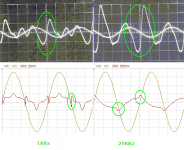
I am add this picture to understanding why Hawkford's error correction only did small help at increasing linearity.
The circle sign is where it will be very difficult to be removed, it is different if we using class A, the mosfet will be more linear by itself, also happened to BJT.
The circle sign is where it will be very difficult to be removed, it is different if we using class A, the mosfet will be more linear by itself, also happened to BJT.
Attachments

you can easily "prove your assumption" by not thoroughly "debugging" a sim, stopping short when it looks like your expectations - Bob's EC shouldn't show that much crossover error
the TL081 output really sucks, and I Like op amps - it shouldn't be used here, and without some other additional compensation provisions bootstrapping any op amp like that is going to have stability issues
why aren't you R-C or C multiplier filtering the boosted supplies? - modeling the supply inductance to the output Q is good but no one would spend for boosted supply then "cheap out" by not RF filtering to break any possible high frequency local feedback loops through the power supply coupling that could destabilize the amp
there are other sims of Bob's version of error correction that show a little better performance
I played with Bob's error correction in sim, in
http://www.diyaudio.com/forums/soli...nterview-error-correction-73.html#post1062892
(models of the sim: http://www.diyaudio.com/forums/soli...terview-error-correction-248.html#post1325081 but there's still a few missing...)
I "refreshed" the sim with some models from Bob's book, and the the IRF240/P9240 pair that are included in Ltspice internal libs
blowing up the difference across the EC stage by 500x this sim doesn't show the crossover error
by editing the output mosfet models to the "C" suffix and using Bob's tweaked models even the "ticks" visible in the EC I/O difference trace are smoothed and attenuated
in the later http://www.diyaudio.com/forums/soli...nterview-error-correction-73.html#post1062892 sim I tweaked the EC local loop gain and reduced simmed distortion by another 4x (Q names will need to be edited)
Attachments
Last edited:
the above sim due to the variations in output mosfet models from the original sim is running at very high ~0.8A bias - very good for mosfet lineatiy - but a little overdone by most recommendations
but as Bob and others have mentioned there is no "optimum" bias for Class AB mosfet outputs - distortion keeps on going down as you move to full Class A
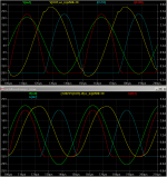
dropping the bias V sources to 8.7 V each gives Bob's recommended ~150 mA with Bob's IRF240C/IRFP924C models - now the EC circuit does show visible "crossover" errors where the output gm changes abruptly when one of the output cuts off - at high frequency that feedback has a hard time dealing with
EC is also a variation on feedback so its no surprise that if there are fairly sharp output stage gain variations there will be limited correction of the higher order harmonics where the feedback loop gain has to roll off
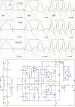
the upper plot is the cordellmosfetamp_2011 with ~ 150 mA output Q bias, shows the larger error at lower bias - more typical of Class AB - note that the yellow plot is the difference across the EC circuit and is only ~ 10 mVpp when you factor in the 500x multiplier
below that I took my later modified higher EC loop gain sim and added a crude "Geometric Mean" bias by replacing output source resistors with 25 A Schottky's in series with each mosfet source and bumping the bias Vsources up to 10.1 V to get back to ~150 mA output bias
the "Geometric Mean" bias gives a smoother transfer from one output Q to the other and the boosted EC loop gain at higher frequencies deals with the error better
showing a more "economical" approach than just high bias
all of these sims are at the "ridiculous" low level of total amp distortion ~4 ppm down to ~400 ppb - many other unmodeled errors beyond these high frequency crossover details will limit real amp performance
but as Bob and others have mentioned there is no "optimum" bias for Class AB mosfet outputs - distortion keeps on going down as you move to full Class A
dropping the bias V sources to 8.7 V each gives Bob's recommended ~150 mA with Bob's IRF240C/IRFP924C models - now the EC circuit does show visible "crossover" errors where the output gm changes abruptly when one of the output cuts off - at high frequency that feedback has a hard time dealing with
EC is also a variation on feedback so its no surprise that if there are fairly sharp output stage gain variations there will be limited correction of the higher order harmonics where the feedback loop gain has to roll off
the upper plot is the cordellmosfetamp_2011 with ~ 150 mA output Q bias, shows the larger error at lower bias - more typical of Class AB - note that the yellow plot is the difference across the EC circuit and is only ~ 10 mVpp when you factor in the 500x multiplier
below that I took my later modified higher EC loop gain sim and added a crude "Geometric Mean" bias by replacing output source resistors with 25 A Schottky's in series with each mosfet source and bumping the bias Vsources up to 10.1 V to get back to ~150 mA output bias
the "Geometric Mean" bias gives a smoother transfer from one output Q to the other and the boosted EC loop gain at higher frequencies deals with the error better
showing a more "economical" approach than just high bias
all of these sims are at the "ridiculous" low level of total amp distortion ~4 ppm down to ~400 ppb - many other unmodeled errors beyond these high frequency crossover details will limit real amp performance
Attachments
Last edited:
I am add this picture to understanding why Hawkford's error correction only did small help at increasing linearity.
The circle sign is where it will be very difficult to be removed, it is different if we using class A, the mosfet will be more linear by itself, also happened to BJT.
Hi
A while ago I made a mock up real HEC circuit and used the function generator as the input so there is no global loop. Here is a link, posts 22 - 27. One reason the Hexfet works better in class A is because the load line never traverses through the low transconductance region near cut off. This 'Gm drop zone' can create lots of distortion. You can see in the link the change in slope of the error signal is greatest at the current crossover. Post 47 shows what the error looks like with an underbias situation.
Last edited:
Hi Jcx, Thanks for the models,
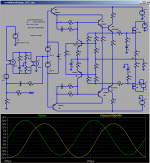
Inductor is used to vibrate whole circuit including its driver in purpose to examining what the system do to maintain it.
This is just hawksford's EC, bob using this and a global NFB for another EC. I post some picture from Mosfet Amp paper before global EC applied, and my simpler similar EC result.
Ooops the picture is not showing up...
I reupload it (the picture).
May be using series amplifier has most benefit for linearity reasons, classA stage use only 3V supply or less. By using this fast driver to track the output of classA. In classA operation 0.000x is very easy to achieve only with simple local feedback.
Hi CBS, that HEC (that link) isn't optimum, you need to tweak it again until reaching most distortion is in crossing region.
Attachments
Last edited:
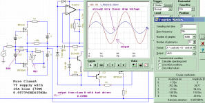
Here it go! ClassB Driving ClassA with simplest one, battery biased only classA stage, no oscillation, no complex circuitry, no difficult tuning, no EC, no underbias situation, no thermal drift, no complex calculation too, Just as it is all natural. Umm, may be too much talk/wrote.
OK this one is example simulation result of DMOS in classA operation, I have another example with only 1.5V supply and 5A bias in this thread:
http://www.diyaudio.com/forums/solid-state/182492-exotic-classa-amplifier-never-seen-before.html
OK this one is example simulation result of DMOS in classA operation, I have another example with only 1.5V supply and 5A bias in this thread:
http://www.diyaudio.com/forums/solid-state/182492-exotic-classa-amplifier-never-seen-before.html
Attachments
Sorry guys, I cannot use this summing (hawksford's or Bob's) EC. I can't make this EC work better for 10KHz and up. I think it is coming from MOSFET gate charging characteristics. I am using SPICE Level-3 model instead of Level-1 and using IRF540 instead of IRFP240, because I need a fair simulation that work when I built it.
If you have any trick at high frequency for this EC, please suggest. I am going to use current feedback error correction.
If you have any trick at high frequency for this EC, please suggest. I am going to use current feedback error correction.
Attachments
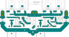
Example PCB layout.
...
No one interested to this driver?
Its all right.. then it is just for my own at least.🙄
Current feedback EC is finished, now I am continuing in finishing PCB.
Thanks a lot, for CBS240 and jcx🙂.
...
No one interested to this driver?
Its all right.. then it is just for my own at least.🙄
Current feedback EC is finished, now I am continuing in finishing PCB.
Thanks a lot, for CBS240 and jcx🙂.
Attachments
Last edited:
- Status
- Not open for further replies.
- Home
- Amplifiers
- Solid State
- FAST and SIMPLE driver for HEXFETS (linear use).