5x.75"=3.75", about 15% of 25", material thickness does add up.Also not taking material thickness into account
Is the excursion in the sim in post #39 at Xmax?
EDIT: And the current vented box model for comparison, sorry I have not done actual measurements yet
You lost me at 4am so I missed this edit. To do a real comparison do this sim in Hornresp too. Then you know they were simulated using the same math and assumptions and you can even overlay the graphs for each design to compare them. There are 3 different ways to sim a ported box with Hornresp, some methods are better for some purposes.
1. Set to Nd, fill in vrc and lrc, ap and lpt.
2. Set to Nd (or Od), define the rear chamber with vtc and atc, and define the port with segments - this allows you to sim flared ports and other shapes of port with up to four segments (the throat chamber as the rear chamber and then the four regular segments for the port).
3. Set to Od, define the box with the first two segments, define the port transition with a .01 length segment and define the port with the final segment - this allows you to sim mltl. But it should be said that there are better programs for simulating mltl.
Yes I have a BW 48 @ 20hz on the minidsp currently, but obvi I can change it to 30 or whatever I need 🙂
Your model says your current box is ported to 38.8 hz. If that is reasonably accurate, having your hpf at 20 hz probably isn't going to be much better than not having it at all. Excursion skyrockets just below tuning, that needs to be shut down. Sim the ported box in Hornresp and use the Filter Wizard to see what frequency you need to set the hpf at to protect the driver from exceeding xmax below tuning, you will likely need to raise it up quite a few hz.
Changing the hpf is going to change the sound so the next step is to go out and listen to the system with the new hpf setting and see if you can tolerate it now that the bass is strangled. Just by looking at graphs it doesn't look like it should make a whole lot of difference but it does sound a lot different. This may make you re-evaluate your F3 goals for future designs if you don't like the sound it makes when properly filtered.
... can you explain what you mean by keeping S1 close to the throat side tap? L12?
Yes, L12 as short as possible, just long enough so the driver fits in the box. But your latest model looks like you've got this figured out.
WOOF!!
Very good. Just a couple of points. L12 and L34 (or L45 if you are using a 4 segment model) don't have to be equal if you don't want them to be. There are folding methods you can use in which the first and last segment lengths can be very different. Also, it looks like your F3 is dropping with every sim. That's fine if you want a lower tuning but if you want more efficiency instead of a lower tuning that's possible too.
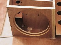
A very rough mockup.
S areas are actual as well as L12 & L34. Horn path 333cm, so some room to work with.
Also not taking material thickness into account
Box dims in inches are roughly 36w x 22h x 36d with a couple inches added for material thx (I upped my max box dims to 39wx25hx36d)
It's time to consider the material thickness and add in bracing. If you want to keep this layout you will need some solid bracing along the horn path to break up the side to side resonances. I'd do at least two and maybe even four braces, so with the side panels included that reduces your effective width by 3 to 4.5 inches. That's a substantial reduction in cross sectional area so it's best to think about it now.
Another option to consider is changing the layout as I mentioned, making the drivers vertical instead of horizontal. That will prevent cone sag and it will also make the mouth much more square, eliminating the need for a lot of the solid bracing to break up the side to side resonance. In fact a lot of bracing can be eliminated compared to the other layout since this layout will be naturally stronger (less unsupported large panels). This type of fold can look very interesting too. Here's a quick pic of what this could look like from a top/down view. Obviously not to scale and it might not work out exactly as pictured, you might need to play with it a bit to get it to work. And this is only one option, there's a bunch of different layouts you could consider.
An externally hosted image should be here but it was not working when we last tested it.
Last edited:
I love that layout design. I didn't know what you meant initially by make the drivers vertical.
I really love that layout a lot, and I will definitely make it vertical.
So how do I calc dims for this layout? Which measurements should I divide in half or none at all? That is the only thing that confuses me.
Dropping F3 is a secret love of mine, and my initial intent was to have it somewhere around 35 or even lower if possible. 130db sounds right on the money.
Also with this design I was hitting xmax somewhere around 30hz or less, I'll have to look at it.
I'll do the vented box sim as well.
I'm just going to keep thanking you all over and over again, this is becoming very exciting and I would not have gotten this far so easily without you
Here is the displacement graph for the previous model.

Also would anyone mind double checking my driver settings? I feel rather unsure about them


Also would anyone mind double checking my driver settings? I feel rather unsure about them
So how do I calc dims for this layout? Which measurements should I divide in half or none at all? That is the only thing that confuses me.
Design it as a single driver box if that makes it easier, just cut the pic in half and design that half with a single driver. Then mirror image the other one and take out the divider panels (bottom panel).
Also with this design I was hitting xmax somewhere around 30hz or less, I'll have to look at it.
I'll do the vented box sim as well.
Here is the displacement graph for the previous model.
Run both designs through the filter wizard. This is going to change things a lot for your current box. Setting the hpf properly will control your excursion, you shouldn't be seeing xmax with the limited power your amp has. It will change the sound, you might not like it after it's properly filtered.
Also would anyone mind double checking my driver settings? I feel rather unsure about them
If those are the same specs I used in my sim (on the first page of this thread), I input them myself. Input Sd, then double click the CMS box, enter VAS into the wizard, double click the MMD box and enter Fs into the wizard, enter Re, double click the Bl box and follow the wizard, and so on and so on. It's almost impossible to screw it up.
Last edited:
Okay cool- that is exactly what I did, too. Thanks for the method check.
Vented simulation

Tapped Horn simulation

Vented simulation
Tapped Horn simulation
Sim for single driver, dividing throat areas in half and leaving horn length the same


Cannot find the filter wizard, that is in hornresp right?
Cannot find the filter wizard, that is in hornresp right?
Okay I did a model for the fold pattern you mentioned, guy.

Horn length is 322cm. S areas match. The only thing is that it flares kind of weird as it approaches the mouth, with a sharp increase in throat area, I don't know if this will be a problem or if the size of the driver will balance it out? I'm hoping so. Also drivers would need to be recessed half the width of the material
Final outer box dims are 39"w x 21.5"h x 30"d
the driver doesn't take up the full space of the basic loft I created, it is made from the driver's rim diameter to the magnet diameter & depth

Well, I messed something up- bad. I was calculating S3 for two drivers instead of one... 977 S3 only gives me 3" of clearance with a 20" height 😛
That would explain the funky flare
That would explain the funky flare
double dumb... I was converting cubic cm to cubic inches instead of area.. So it's not back to the drawing board yay
I feel like a dumb now
I feel like a dumb now
Cannot find the filter wizard, that is in hornresp right?
From the input screen click "Calculate". Don't go into the loudspeaker wizard.
Go to the Acoustical Power Screen in the Window Menu.
Go to Filter Wizard in the Tools menu.
You want to select Active, High Pass and on the Displacement window set your filter order and play with the frequency until you don't exceed xmax at any frequency.
I have a couple more comments but I'm just getting home now. The filter wizard should keep you busy for awhile anyway.
I'm seeing a 48dB @ 28hz. This is 49V (600W @ 4ohm or half of what my max will be)


Wow that little tool is pretty buried in there yet so super helpful. Thanks again
Wow that little tool is pretty buried in there yet so super helpful. Thanks again
Sim for single driver, dividing throat areas in half and leaving horn length the same
Okay I did a model for the fold pattern you mentioned, guy.
Horn length is 322cm. S areas match. The only thing is that it flares kind of weird as it approaches the mouth, with a sharp increase in throat area, I don't know if this will be a problem or if the size of the driver will balance it out? I'm hoping so. Also drivers would need to be recessed half the width of the material
Final outer box dims are 39"w x 21.5"h x 30"d
Ok, first thing - I think you are confused about what a throat is. The throat is the cross sectional area at the beginning of the horn (S1). At least that's what I call the throat. In offset driver designs like this some people may refer to the throat as S2, the driver tap point, I'm not sure. I think what you mean to say is flare, not throat. Either way, maybe we should both just stop saying throat.
Next, your mouth side tap cross sectional area (S3 in your 3 segment sim) needs to be big enough to fit the driver, plus at least an extra inch if it vents through the backside.
20 inch internal height = 50.8 cm
driver mounting depth = 19.43 cm (from your picture)
50.8 x 19.43 = 987.044 sq cm is the ABSOLUTE minimum value for S3
BUT if the driver vents through the back I would add another inch at least.
50.8 x (19.43 + 2.54) = 1116.076 sq cm is a more ideal S3
You don't want to start recessing the drivers into the baffle. Make S3 bigger instead.
And finally, that big step in area as you round the last bend is what happens when you try to make a sim fit into predetermined dimensions. This is going to happen, it's why several iterations are sometimes necessary for complex folds. When this happens you have options. Change the sim to match the drawing and see if the new sim is acceptable or start drawing a new layout to better match the sim.
The size of the driver is not going to balance out that big step in cross sectional area after the bend. In a small design like this the driver ideally should be accounted for since it chokes the flare at that point but that is a job for Akabak, not Hornresp.
Well, I messed something up- bad. I was calculating S3 for two drivers instead of one... 977 S3 only gives me 3" of clearance with a 20" height 😛
That would explain the funky flare
Not sure if you made a mistake or not, but see my immediately preceding comments on S3 size and fold iterations. Not sure where are getting the 3 inch clearance figure.
double dumb... I was converting cubic cm to cubic inches instead of area.. So it's not back to the drawing board yay
I feel like a dumb now
I have no idea what you were doing, you may or may not have made a mistake. But folding a complex design into predetermined dimensions will make you feel dumb a few times. But when it all works out it's worth it.
I haven't said much about folding yet but I will address the topic soon since you are already drawing up plans.
Last edited:
That all makes complete sense.
Yeah ignore the dumb comment. I went back to double check my dims and converted some stuff wrong. Then I realized my double check was wrong and that everything was a-ok.
I am already working on a sim with larger S3, and a different folding pattern that folds a lot easier in that space. Luckily I can increase/decrease the depth and height to accommodate the folds, my outer dimensions are not entirely locked up


To me it seems like a better direction, and I think it looks cooler 🙂 No more recessing either.
Yeah ignore the dumb comment. I went back to double check my dims and converted some stuff wrong. Then I realized my double check was wrong and that everything was a-ok.
I am already working on a sim with larger S3, and a different folding pattern that folds a lot easier in that space. Luckily I can increase/decrease the depth and height to accommodate the folds, my outer dimensions are not entirely locked up
To me it seems like a better direction, and I think it looks cooler 🙂 No more recessing either.
You're a saint!
Wow that little tool is pretty buried in there yet so super helpful. Thanks again
If you want to thank someone the real hero in this story is David McBean, the author of Hornresp. He's a member of this forum. Stop by the Hornresp thread (it's usually near the top of the Subwoofer subforum) and let him know what you think. He spends a LOT of time doing constant updates, new features and he actually listens to feedback from users on a daily basis. He doesn't get enough credit. You are giving me too much.
If it wasn't for Hornresp you would be doing this in Akabak. Believe me, you wouldn't want that.
You don't want to start recessing the drivers into the baffle.
Recessing is not bad if it's planned for in the design. It definitely helps to center the driver over the hole if a bit of recess is accounted for in the design of the baffle. As even a minor leak at this point will greatly reduce LF output, recessing the driver a bit can minimize if not eliminate the possibility of this happening. For my POC3 I just bonded two 1/2" ply panels together to form the baffle, and made the cutout in one slightly bigger than the other to allow the driver to be recessed. It worked out very well.
Attachments
To me it seems like a better direction, and I think it looks cooler 🙂 No more recessing either.
I like the other way better, this new design bundles all the internal panels to either side whereas they were spread out more in the previous design. More spread = better natural bracing without actually adding bracing. This new design has a massive unbraced open area in the middle and it would be difficult to add bracing in there. You can't put any in front of the drivers or you won't be able to access them. You could put a bit behind the drivers but it still wouldn't be as well braced as the other design with no added bracing at all.
Also I think the other way looks better, but that hardly matters.
Now can you take a quick break with all this CAD'ing so I can address folding? Unless playing with CAD is fun for you. You're making me feel dumb putting up fully CAD'ed designs faster than I can comment on them.
Considering that there are six folds in that suggested design, I suggest using the "advanced centerline" approach for measuring the path length of the horn.
- Home
- Loudspeakers
- Subwoofers
- FaitalPRO 15HP1060 vs 3015LF for tapped horn?