Plenty of choices.
Just look for a 3mm LED with a tinted lens, e.g. TLHB4200.
You can also choose the emitted light wavelength.
Inclusing blue (430~480nm), cyan (520nm), and turquoise (500nm).
Patrick
Just look for a 3mm LED with a tinted lens, e.g. TLHB4200.
You can also choose the emitted light wavelength.
Inclusing blue (430~480nm), cyan (520nm), and turquoise (500nm).
Patrick
Vishay TLHB4200 looks like a nice blue LEDs with a wide wavelength spectrum.
Vishay TLHB5400 of 5mm LEDs looks also similar.
Thank you!
Vishay TLHB5400 of 5mm LEDs looks also similar.
Thank you!
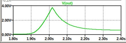
I have a sim made up.Tell me how you displayed this graph and i'll try my rendition and see what happens.
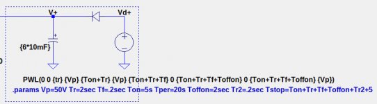
I used an oversimplified power supply simulation. The rectifier and capacitors are used as a simplistic model for the voltage decay when the power is turned off. The rise time Tr is a simplistic ramp for the power on voltage, including effects due to the CL-60 inrush current limiter on the transformer primaries.
Attachments
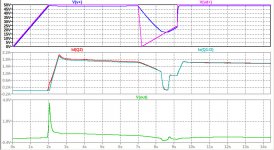
Maybe showing more plots will help.
- The top plots are Vd+,the output from the PWL voltage source, and V+ the rectified/filtered voltage.
- The second plots are the FET currents Q2, the IRFP240 and Q1, the SemiSouth R100.
- The third plot is the output voltage.
Attachments
4V is not really that concerning for a brief turn on thump.
I am not going to discuss how to fix these issues in a thread advertised the way it is.
I am not going to discuss how to fix these issues in a thread advertised the way it is.
Last edited:
We're gonna need more PCB pics. 🙂
Even if you have more PCB images, there are still some unknowns about the active devices, such as the 2SJ74 gm at its operating point, and the SemiSouth R100 Vgs and gm at its operating point.
Your post makes me laugh 😀 Happy Holidays Merry ChristmasWe're gonna need more PCB pics. 🙂

 Best wishes of joy, health and prosperity
 Hope Michael give a talk at BAF in 2021 ?
2020 Burning Amp Festival
Indeed!
:--))
Moreover I have the impression that 6moons reviewers have not the enthusiasme Herb Reichert showed. Much talking around......The last more enthusiastic review they did was F7.
:--))
Moreover I have the impression that 6moons reviewers have not the enthusiasme Herb Reichert showed. Much talking around......The last more enthusiastic review they did was F7.
:--))
I really mean their kind of writing!
And I confess that I feel like Sherlock Holmes looking at the partial information the pictures give.
A kind of crossword puzzle for the brain, making me really nervous.
Like the Christmas gifts on the wardrobe I wanted to look at as a child, judging from shape, what it could be.
Last edited:
Wanted to meet Aslan but ended up in Pass land instead. 😉... the wardrobe I wanted to look at as a child, ...