I bought my girlfriend a train ticket to Paris so I could work on my amp. 😄Thanks!
I finished it when my wife was out for a weekend with her friends when she was eight months pregnant with our first child.
I've got two kids now, so my free-time now is much more limited. I just noticed a popsicle stick managed to make it's way under the left outputs. 😂
View attachment 1070783
If only my cats wouldn't lie on my parts and tools 🤣
Hi guys, I almost finished my F6 today when my right channel assembly went wrong.
don’t know why I removed the dim bulb tester. Thinking that since the left channel was good, the right side must be too! overconfident. Pop went the jfets! It shot a neat string of cloud across the bench🤣 I ordered a new quad set from the store few hours ago, and I just got notification that it’s been shipped. Insanely good.
I may have reversed the polarity. But after checking the wires it seemed I did not? I used green wires for v+ red for v- and black for ground.

the opposing side of the power supply to the shot right F6 board (left supply) is now dead outputting 38mV at the V+ To ground terminals, while right side still outputting 25v steady with its LED still lit.
I tested all supply resistors by lifting up one leg, all were still good including bleeders and led limiters. So it must be one or all of the 4 supply caps that also blew Along with jfets.
tomorrow morning I’ll have to disassemble it all.

Questions for the experts or someone who had this happened:
cl-60 to ground. 2 fuses of 250v 1.5A installed In switch carrier.
i rushed and paid the price. Feeling a lil defeated today. Any criticisms, comments and insights welcome
don’t know why I removed the dim bulb tester. Thinking that since the left channel was good, the right side must be too! overconfident. Pop went the jfets! It shot a neat string of cloud across the bench🤣 I ordered a new quad set from the store few hours ago, and I just got notification that it’s been shipped. Insanely good.
I may have reversed the polarity. But after checking the wires it seemed I did not? I used green wires for v+ red for v- and black for ground.
the opposing side of the power supply to the shot right F6 board (left supply) is now dead outputting 38mV at the V+ To ground terminals, while right side still outputting 25v steady with its LED still lit.
I tested all supply resistors by lifting up one leg, all were still good including bleeders and led limiters. So it must be one or all of the 4 supply caps that also blew Along with jfets.
tomorrow morning I’ll have to disassemble it all.
Questions for the experts or someone who had this happened:
- What could cause the opposing side damage from supply board to F6 board? Wrong polarity? A Simple short?
- other items that would potentially be blown and worth replacing. From observing earlier posts, the items at risk are IRFP240s, source resistor, and sometimes zeners.
- If I were to replace IRFP240s from the kit, which drop-ins do you currently recommend?
- Using the DC bench supply to test the shot board, I assume 25v positive goes to v+ and ground is ground. Do I need a V- connection in order to measure correct voltages across resistors? How does one test without risking further damage😢 to mosfets and jfets. I assume the bench supply will need dual output pair when mine only has one pair.
cl-60 to ground. 2 fuses of 250v 1.5A installed In switch carrier.
i rushed and paid the price. Feeling a lil defeated today. Any criticisms, comments and insights welcome
1. yes and yes. I assume that you have a DMM, otherwise it will be very hard to adjust an F6 anyway. Disconnect the power supply wires and measure, don't look.
2. IRFP:s and source resistors. Zeners are very hard to damage provided no other short is present on the board.
3. Use the same type of mosfets on both channels.
4. Yes, you will need a -V as well. Provided that the bias is tuned down to a minimum you should be able to use a 100 ohm resistor (or slightly less) in series with +V and +V and have a fully working amplifier. You would even be able to play music on it (not very loud...). If I remember correctly the F6 will work as an amplifier from ca +-10V and upwards.
That stinks. Were the JFETs in the correct spots? Referencing to ground using a mono supply, you should have positive to both sides so long as the power supply wires are hooked up right. How are you checking between your + supply voltage on the left board and ground?
Have you checked all the solder work? Are there perhaps any 'bridges' or shorts (e.g. FETs or MOSFETs)?
Thanks Strongbow60.1. yes and yes. I assume that you have a DMM, otherwise it will be very hard to adjust an F6 anyway. Disconnect the power supply wires and measure, don't look.
2. IRFP:s and source resistors. Zeners are very hard to damage provided no other short is present on the board.
3. Use the same type of mosfets on both channels.
4. Yes, you will need a -V as well. Provided that the bias is tuned down to a minimum you should be able to use a 100 ohm resistor (or slightly less) in series with +V and +V and have a fully working amplifier. You would even be able to play music on it (not very loud...). If I remember correctly the F6 will work as an amplifier from ca +-10V and upwards.
1. I have a DMM and have measured before connecting, that indeed the wires from v- reading goes to v- board connection. this picture is from the v- terminal to ground measuring -25.15v. The opposite side (left) had identical inverted +25.15v before being blown up.
2. Ordered a new set of the 3w source resistors just in-case. I did retest them today and they seem to be fine on the ohmmeter at the moment.
3. I currently have 4 of these on hand IRFP150 is this good enough? or these IRFP250 ? local shop stocks both.
4. Sorry I didn’t understand this part where “v+ to v+ In series with 100 ohms between”, you mean this 100ohm load works on a regular 2 lead switching supply without v-? But I managed to ask an old friend a favor, and he does have a 4 channel bench supply available where it can do the fancy internal series connection thingy with complete (V+ G V- ) output which he’s lending me this week!!! It will be very helpful In debugging the board. Will post when it gets here for testing.
Hey Mike, the Jfets sure are in the correct spots. The DMM reports correct voltage and polarity at the terminals on both sides pre-smoke puff per the above pics. I also checked for mosfet leg shorts or any shorts to heat sink but it was well insulated. No continuity to sink.That stinks. Were the JFETs in the correct spots? Referencing to ground using a mono supply, you should have positive to both sides so long as the power supply wires are hooked up right. How are you checking between your + supply voltage on the left board and ground?
Freebee, my soldering skills sure needs work, but I did not see a drippy bridge on the legs. The back side of the mosfets wasn’t reflowed as well as the front tho.Have you checked all the solder work? Are there perhaps any 'bridges' or shorts (e.g. FETs or MOSFETs)?
will keep checking tomorrow, but whatever it is another face palm sure is waiting for me when I find out 🤣
thanks again guys.

Check back what @Mikerodrig27 wrote about the difference in mosfets. I can attest to his findings about sound quality for FQH44N10 and for IRFP150. It all depends on the rest of your system. If it is on the bright side, go for FQH44N10, else use IRFP150 (a simplified reasoning).
The point of using a 100 ohm resistor is best illustrated by attached picture. Since you will have a bench power supply this will possibly be moot. Start off by limiting current (if possible) and use +-10V and go up.

The point of using a 100 ohm resistor is best illustrated by attached picture. Since you will have a bench power supply this will possibly be moot. Start off by limiting current (if possible) and use +-10V and go up.
@strongbow60 much appreciated for the picture. Very easy to understand. Did you just drew that in a program for me? That’s awesome. I learned a lot thank you.
I think this could be the short. Before reflow there's barely any space. In fact, if I recall the smoke explosion, it looked a lot like solder flying from the small bridge. The Jfets casing is intact with no burns. I have since cleaned the boards and about to go into testing the Jfets individual health.

after hot air reflow below

@Mikerodrig27 I may have found the “short“ above. It could be dried rosin reflecting, but the first picture the spacing was less than 0.1mm Before reflow. And also a question for you on the IRFP150. It appears I have IRFP150NPBF version, and FQH44N10 is no longer available. Seems similar enough but I don’t want to assume things. Based on the data sheet, do you and others think this okay on slightly lower input capacitance specs?


I think this could be the short. Before reflow there's barely any space. In fact, if I recall the smoke explosion, it looked a lot like solder flying from the small bridge. The Jfets casing is intact with no burns. I have since cleaned the boards and about to go into testing the Jfets individual health.
after hot air reflow below
@Mikerodrig27 I may have found the “short“ above. It could be dried rosin reflecting, but the first picture the spacing was less than 0.1mm Before reflow. And also a question for you on the IRFP150. It appears I have IRFP150NPBF version, and FQH44N10 is no longer available. Seems similar enough but I don’t want to assume things. Based on the data sheet, do you and others think this okay on slightly lower input capacitance specs?
Jfets cooked. 100ohm (99 actual) in 9v test circuit yielded
Q3 = 6.84v
Q4 = 4.55v
way off 🤣
all 3W resistors survived.
tomorrow will test the IRFPs
new jfets sets arrive Monday

Q3 = 6.84v
Q4 = 4.55v
way off 🤣
all 3W resistors survived.
tomorrow will test the IRFPs
new jfets sets arrive Monday
Outch, not good!
Besides, as a personal observation, I think that you are using to much solder on each joint. Each hole is plated through, It requires just a small amount on each joint on one side only.
A solder joint should be smooth, a few (less than five) seconds for most joints. For the bigger resistor and mosfets it will unfortunately take longer (or turn up the heat or use another point). The reason is that the wide copper traces will transfer away heat very fast.
Yeah I just saw an old post of Zen Mod in the aleph J thread saying the same thing to someone else having a short. Welp, lesson learned! will be gentle with the rebuild.Outch, not good!
Besides, as a personal observation, I think that you are using to much solder on each joint. Each hole is plated through, It requires just a small amount on each joint on one side only.
A solder joint should be smooth, a few (less than five) seconds for most joints. For the bigger resistor and mosfets it will unfortunately take longer (or turn up the heat or use another point). The reason is that the wide copper traces will transfer away heat very fast.
I used the Infineon from Arrow. I will say that they were also very closely matched which was a nice perk (although not necessary)
for soldering, I use a Hakko FX888. It has no problem getting 3w resistors soldered within a few seconds although they can take a little heat. Cardas eutectic solder makes soldering very easy too.
for soldering, I use a Hakko FX888. It has no problem getting 3w resistors soldered within a few seconds although they can take a little heat. Cardas eutectic solder makes soldering very easy too.
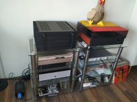
Very nice! I see you went for the big boy case! Kind of wish I had done that as there are a bunch of projects that use that case as well. Will be nice for down the road. 575 should run very cool with a stock power supply
It's dual mono under the bonnet and uses the Tea-bag power supplies. Doesn't sound half bad 😸.
Hello
I have the Rev .2 set of boards. On each is the space for a large resistor that is unlabelled. Would this be a leftover from a previous version?
It does not appear in the BOM. Wayne
I have the Rev .2 set of boards. On each is the space for a large resistor that is unlabelled. Would this be a leftover from a previous version?
It does not appear in the BOM. Wayne
Find that my F6 is detailed, however is not as dynamic as I had hoped. Could it be a mismatch with my Perreaux SM3 preamp? Or will the sound change after 100 hours or so? Have upped the bias from 575mv to 700mv.
- Home
- Amplifiers
- Pass Labs
- F6 Illustrated Build Guide