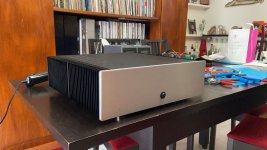
Hi everyone, in these days of quarantine I have taken advantage of it to make the Firstwatt F6.
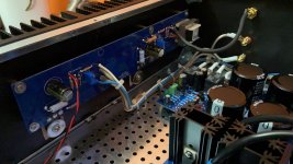
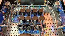
My realization is exactly as in the manual, without any modification or improvement, that is, as thought by its designer, Mr. Pass. The PCBs are those of the DIY Store and I decided to add the soft start & Speaker soft start and dc protector also on diyaudio store. The components of the amplifier are those of the kit while those for the PSU and the protections come from Mouser, the transformer is a 400Va toroidal produced by Toroidy.
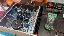
The construction was easy and did not present any problems, thanks to the fantastic guide of 6L6 and to the comments of all of you, frequenters of this great forum, specifically I found two comments very useful as a neophyte, which removed me from the only doubts that I faced:
- During the calibration of the bias, measuring the voltage across the resistor R2 I had 0mV and I thought I had done something wrong, but reading in the forum, thanks to the BruceInOz message # 1633 I understood that the mosfets need a certain voltage on the gate to make them start working and in our case it must be around -23V, a value that I reached by acting on the P2 trimmer.
- Always trying to reach the bias value of corca 500mV at the ends of R2, I realized that I did not reach this value, but only 280 / 330mV, always reading on the forum (thanks to kbergsson and 6L6, messages 1123 and 1125) I understood that I had to use 6.1 / 6.8V zener, changed which, I calibrated the bias correctly.
A tip for beginners like me is that the calibration must be done in sequence first the bias, then offset, then bias again and then offset, so on until the two values are correct, because one adjustment affects the other.
It has been working for a couple of weeks now and I am very happy with it, the sound amuses me a lot, the music has taken on a thickness that it did not have before, I sincerely thank Mr. Pass for giving me the opportunity to replicate one of his projects and 6L6 for having drafted this guide and all of you for helping me, by giving me the container and for your comments from which I took the advice.
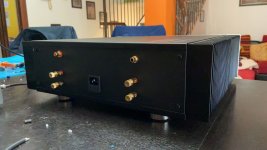
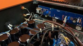
I am attaching some photos of my realization.
Thanks again to everyone and enjoy!
My realization is exactly as in the manual, without any modification or improvement, that is, as thought by its designer, Mr. Pass. The PCBs are those of the DIY Store and I decided to add the soft start & Speaker soft start and dc protector also on diyaudio store. The components of the amplifier are those of the kit while those for the PSU and the protections come from Mouser, the transformer is a 400Va toroidal produced by Toroidy.
The construction was easy and did not present any problems, thanks to the fantastic guide of 6L6 and to the comments of all of you, frequenters of this great forum, specifically I found two comments very useful as a neophyte, which removed me from the only doubts that I faced:
- During the calibration of the bias, measuring the voltage across the resistor R2 I had 0mV and I thought I had done something wrong, but reading in the forum, thanks to the BruceInOz message # 1633 I understood that the mosfets need a certain voltage on the gate to make them start working and in our case it must be around -23V, a value that I reached by acting on the P2 trimmer.
- Always trying to reach the bias value of corca 500mV at the ends of R2, I realized that I did not reach this value, but only 280 / 330mV, always reading on the forum (thanks to kbergsson and 6L6, messages 1123 and 1125) I understood that I had to use 6.1 / 6.8V zener, changed which, I calibrated the bias correctly.
A tip for beginners like me is that the calibration must be done in sequence first the bias, then offset, then bias again and then offset, so on until the two values are correct, because one adjustment affects the other.
It has been working for a couple of weeks now and I am very happy with it, the sound amuses me a lot, the music has taken on a thickness that it did not have before, I sincerely thank Mr. Pass for giving me the opportunity to replicate one of his projects and 6L6 for having drafted this guide and all of you for helping me, by giving me the container and for your comments from which I took the advice.
I am attaching some photos of my realization.
Thanks again to everyone and enjoy!
Attachments
F6 stays on regardless of power switch.
Hi, finished this build a couple of months ago and it sounds great. I noticed yesterday that now when I turn off the main power switch the amp keeps playing ! Also noted that the LED's on the amp boards are on when the power switch is on, and fade out slowly when I turn the power switch off - but- the amp keeps making music - for hours, it's clearly not the caps draining out.
I'm stumped; any ideas ?
It had worked normally until yesterday.
thanks- it sounds fine btw.
I guess I could right at the output of the switch...can't figure why the LED's on the amp boards dim and go out though once I turn the power switch off- yet the amp keeps playing? The LEDS indicate no power on the amp boards when they're off (I assume) yet clearly there's power and signal there?
thanks
thanks

pretty funny
So...chalk this one up as a new one. I updated my Roon system over the weekend and added a Nucleus and renamed some end points. One of which were a pair of Sonos mounted on the wall above the Klipsch RPM600 that the F6 runs via a bluesound node. I called both the node and the sonos "Gym" - when I thought the F6 was running without any power it was really the Sonos right above the Klipsch lol !
I renamed them and everything works fine. Duh !
Pretty funny and bizarre right ? LOL
Yep 😀, and good that you identfied the real "culprit" before going hammer and tongs trying to troubleshoot the amplifier.

Hi all. Have my F6 power supplies all wired up in the chassis and working. The concern I have before populating the F6 boards is that I had to use the Antek AS3220 Transformer as the 3218 was out of stock. This has resulted in unloaded rail voltages of +-27V. Am wondering what impact this has on the Zener and R7 - so I did some math. Don't have a 9v Zener so using 6.2v.
The spec on the 1N4735A Zener gives current of betyween 2.5 and 76ma if I'm reading correctly. So I would have 26v (loaded rail assumption) - 6.2V = 19.8v across R7. The current through the pot will be 6.2/5000 = 1.24ma. The minimum current for the zener is 2.5ma so the total current through R7 must be at least 3.74ma (call it 4ma). Thus R7 can be no more than 19.8V/4ma=4950 ohms. So I am thinking a 3.3K R7 will work here. What say all of you?
The spec on the 1N4735A Zener gives current of betyween 2.5 and 76ma if I'm reading correctly. So I would have 26v (loaded rail assumption) - 6.2V = 19.8v across R7. The current through the pot will be 6.2/5000 = 1.24ma. The minimum current for the zener is 2.5ma so the total current through R7 must be at least 3.74ma (call it 4ma). Thus R7 can be no more than 19.8V/4ma=4950 ohms. So I am thinking a 3.3K R7 will work here. What say all of you?
Hi all. Have my F6 power supplies all wired up in the chassis and working. The concern I have before populating the F6 boards is that I had to use the Antek AS3220 Transformer as the 3218 was out of stock. This has resulted in unloaded rail voltages of +-27V. Am wondering what impact this has on the Zener and R7 - so I did some math. Don't have a 9v Zener so using 6.2v.
The spec on the 1N4735A Zener gives current of betyween 2.5 and 76ma if I'm reading correctly. So I would have 26v (loaded rail assumption) - 6.2V = 19.8v across R7. The current through the pot will be 6.2/5000 = 1.24ma. The minimum current for the zener is 2.5ma so the total current through R7 must be at least 3.74ma (call it 4ma). Thus R7 can be no more than 19.8V/4ma=4950 ohms. So I am thinking a 3.3K R7 will work here. What say all of you?
I'm using an Antek 4220 with no changes from the BOM, power supply is putting out 27V unloaded. It's been running for a couple of weeks now without any problems. Using the 6.2 zener as well. Interesting to see what responses will be. I would hate to have to pull my boards.
That sounds fine. With your 26V rail assumption, the dissipation of R7 will be about 1/8 W, so don't use too
wimpy a resistor.
wimpy a resistor.
Last edited:
I'm using an Antek 4220 with no changes from the BOM, power supply is putting out 27V unloaded. It's been running for a couple of weeks now without any problems. Using the 6.2 zener as well. Interesting to see what responses will be. I would hate to have to pull my boards.
Are you using R7 = 3.3K also?
The higher supply voltage is only a potential issue for the front end. The JFets are running naked between the rails. The output stage will do well with higher voltage, quiescent current may be adjusted to manage temperature of the heatsinks.
The higher supply voltage is only a potential issue for the front end. The JFets are running naked between the rails. The output stage will do well with higher voltage, quiescent current may be adjusted to manage temperature of the heatsinks.
So given that my loaded rails will most likely be slightly lower than 26V do you think I need to make changes?
That sounds fine. With your 26V rail assumption, the dissipation of R7 will be about 1/8 W, so don't use too
wimpy a resistor.
Dennis, thanks much for the reply. Will watch the wattage.
What is the Idss of your JFets? They will probably be fine, but you may think about their power dissipation.
I built a different front end for mine, because I was planning for higher voltage, and I happen to like the sound of the diamond buffer that I used.
I built a different front end for mine, because I was planning for higher voltage, and I happen to like the sound of the diamond buffer that I used.
What is the Idss of your JFets? They will probably be fine, but you may think about their power dissipation.
I built a different front end for mine, because I was planning for higher voltage, and I happen to like the sound of the diamond buffer that I used.
Not sure on the ldss - they are the B versions from the DIY store. Thanks for the heads up on this.
- Home
- Amplifiers
- Pass Labs
- F6 Illustrated Build Guide