Back to share my achievement with you, I had 2 projects at the same time (Headphone amp Noir) and the F6.
The chassis was entirely made of 5 and 6mm aluminum, the heatsinks come from China (not found better in Europe).
The amp works wonderfully, it is as silent as a grave, no "plop" when starting or switching off, no volume noise at full blast without a source, impressive.
Sound side, it is balanced, beautiful deep bass, in the meantime I received a pair of Focal Chora 826, the marriage is magnificent.
A big thank you to Mr Pass for his sharing and his know-how, and to the forum for your help particularly to "2 Picodumbs"
Hello mokaonli, the amplifier is beautiful, would you be willing to share where you sourced the “box” materials?
I have a silly question......Can someone direct me to the F6 BOM?
I am sure it's there I just can't seem to find it.
I am sure it's there I just can't seem to find it.
Red LED in DiyAudio F6 kit
I just received the components kit from the DIYaudio store and it came with red LEDs rather than blue as noted on the boards also purchased from the store. Any issue with the resistor that is associated with them? Also, with the orientation of the LEDs, am I to assume that the "U1 +" of silk screen notes the positive side?
Are most builder using the higher voltage diodes that come with the kit?
One last question on the transistors. I saw a Youtube build of the F6 and there was a comment on putting thermal paste between the two components that are zip tied together. This is not noted in the build thread as far as I can tell? What is the purpose and does this affect performance?
Thanks and great job on the thread.
I figured out the LED orientation after reading the schematic, cathode (short leg) toward ground.
Nice!
I think I recall that one LED is on the positive rail for one channel, and the other is on the negative rail for the other channel. Check boards against schematic yourself to be sure and install LEDs accordingly. My memory isn't great, but perhaps someone with direct knowledge can confirm.
re: other questions.
V+ positive rail. V- Negative rail.
LED resistor is just for brightness. No worries. Not sure if it was adjusted for blue to red in the kit, but you can adjust yourself if it's too bright/dim for your taste.
Paste between JFETs isn't strictly necessary, nor is zip-tying them together, but it can't hurt and may help. Purpose - thermal tracking between the parts.
Edited - not sure what others needed for the diodes, and I don't remember which I installed. I think 6V0???
Last edited:
Hello,
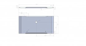
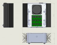
Thank you for your feedback, concerning the case it is 100% made in home, so I am attaching the machining plans to you.
For heatsink, search for "BRZHIFI PASS dedicated heatsink" you will find them quickly.
Thank you for your feedback, concerning the case it is 100% made in home, so I am attaching the machining plans to you.
For heatsink, search for "BRZHIFI PASS dedicated heatsink" you will find them quickly.
Attachments
Interesting Heatsink certainly.
But the shippings are 2X the things' purchase price... 100$
And the F6 is a lowish heat output design.
But the shippings are 2X the things' purchase price... 100$
And the F6 is a lowish heat output design.
Yes, some nicely finished cases but the freight … It's starting to be cheaper, quicker and better to get the parts made locally again or from somewhere else.
And I don't like how they're offering factory built copies of the Pass designs either, with the usual question about parts quality. Buying from China has certainly lost it's attraction these days
And I don't like how they're offering factory built copies of the Pass designs either, with the usual question about parts quality. Buying from China has certainly lost it's attraction these days
For my part, I paid them $ 172, as much postage as the price of the material, the delivery was fast (10 days).
In Europe I couldn't find a model with this design, but the equivalent cost me $ 300, so the choice was quick.
On the efficiency side, no worries on my side, they are not used optimally (horizontally), and I have not placed the MOSFETS at the bottom (my bad).
In Europe I couldn't find a model with this design, but the equivalent cost me $ 300, so the choice was quick.
On the efficiency side, no worries on my side, they are not used optimally (horizontally), and I have not placed the MOSFETS at the bottom (my bad).
Nice!
I think I recall that one LED is on the positive rail for one channel, and the other is on the negative rail for the other channel. Check boards against schematic yourself to be sure and install LEDs accordingly. My memory isn't great, but perhaps someone with direct knowledge can confirm.
I don't have the direct knowledge but I think you remembered correctly, I reoriented left channel LED when it did not lit so I can safely say left channel board LED should be on - rail and installed accordingly.
Regards,
Hakan
Back to share my achievement with you, I had 2 projects at the same time (Headphone amp Noir) and the F6."
Beautiful job on the chassis.
Do the holes on top mimic a spectrum analyzer? If so excellent detail.
Regards,
hakan
I don't have the direct knowledge but I think you remembered correctly, I reoriented left channel LED when it did not lit so I can safely say left channel board LED should be on - rail and installed accordingly.
Regards,
Hakan
To clarify, when I said left channel I meant, viewing from front, input transformers towards back and board on the lefthand side.
Last edited:
Hi Everyone,
This is my first ever amp build! I've been in the hobby since a teenager and worked in hi-fi retail for over 10 years. I'm now 51 and quite excited.. Anyway, I know that this has probably been asked before, but I'm at page 74 and not seen an answer as yet and I want to place the order for some bits.
I just want to check I've got the correct values for a couple of resistors and stuff. They are -
https://www.mouser.co.uk/ProductDetail/625-GBPC3510-E4/
https://www.mouser.co.uk/ProductDetail/527-CL60/
https://www.mouser.co.uk/ProductDetail/71-RL20S-G-3.3K/
DE2E3SA332MA3BY02F Murata Electronics | Mouser United Kingdom
Particularly the Cl-60 and the safety capacitor. Any feedback would be appreciated, thank you.
One other thing. I need a decent'ish soldering station. Can I get away with these -
Soldering Station, 65W Tilswall Solder Station Welding Iron with ℉/℃ Smart Temperature Control (200℃-480℃), Extra 5pcs Soldering Tips, Built-in Transformer, Ideal for School Lab, Hobby, Electronics: Amazon.co.uk: DIY & Tools
https://www.amazon.co.uk/mercury-703-050UK-Ceramic-Soldering-Station/dp/B000L97ZT4
Or would you recommend anything else?
Thank again
I assume your 3.3K is for feeding the zener diodes. You can get a cheaper part
that has higher tolerance and lower tempco, for example:
https://www.mouser.ca/ProductDetail/Vishay-Beyschlag/MBB02070C3301FCT00/?qs=PwR17mNzlcNiVZAjiGDCdg==
The other parts look fine.
I built most of my stuff using a cheap pencil soldering iron so no suggestions
from me. I do like the look of the first one more. 🙂
Good luck with your build.
Dennis
I assume your 3.3K is for feeding the zener diodes.
..and yes, it's for the 6.8v zener 🙂
Questions on grounding...
I see in the build guide on the first page that the speaker return (-) is taken to the signal board PCB. Is this the best approach or is more advisable to take the speaker return (-) to the common star point on the PSU PCB before terminating it to chassis ground via the CL-60?
I also see in the build guide on the first page that the mains ground and CL-60 ground share the same chassis ground point. I was always under the impression that the mains ground should have its own dedicated chassis ground. No?
- Home
- Amplifiers
- Pass Labs
- F6 Illustrated Build Guide