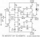
Set them at midpoint.
Yeah I use the Y Pin configured trimpots (Bourns 3299Y series), and on one you need to turn clockwise and the other anti-clockwise.
Just set them in the middle to start.
Yeah I use the Y Pin configured trimpots (Bourns 3299Y series), and on one you need to turn clockwise and the other anti-clockwise.
Just set them in the middle to start.
It is 80ohm-120ohm.So are you measuring from the drain pin to the heatsink?
What is the measured value?
Speaker post dose not touch to chassis.
But speaker post(-) touch indirectly through PSU ground with CL60.
But speaker post(-) touch indirectly through PSU ground with CL60.
Is the drain pin your measuring from connected directly to speaker output or to the power supply?
Each mosfet is different.
Each mosfet is different.
Q1 Drain should be directly electrically connected to the positive rail of the power supply. NOT SPEAKER BINDING POST
Q2 Drain should be directly electrically connected to the speaker output binding post.
Q2 Drain should be directly electrically connected to the speaker output binding post.
Last edited:
If you disconnect the amp from the power supply and then measure the resistance from both the positive and negative rails of the power supply to the chassis what do you get?
Oh, I did not connect from power supply now...
Sorry for ignorance.
I did not disconnect star ground to chassis either.
Sorry for ignorance.
I did not disconnect star ground to chassis either.
Measure with and without star ground connected
1) Measure from star ground to chassis
2) Measure from positive rail to chassis with and without star ground connected
3) Measure from negative rail to chassis with and without star ground connected.
1) Measure from star ground to chassis
2) Measure from positive rail to chassis with and without star ground connected
3) Measure from negative rail to chassis with and without star ground connected.
Last edited:
Without power supply,
Connected star ground/chassis.
Star ground/chassis 12ohm
+ rail/chassis 49ohm
- rail/chassis 44ohm
Dissconnected with star ground/chassis
No connection with star ground/chassis, +rail/chassis -ground/chassis
Connected star ground/chassis.
Star ground/chassis 12ohm
+ rail/chassis 49ohm
- rail/chassis 44ohm
Dissconnected with star ground/chassis
No connection with star ground/chassis, +rail/chassis -ground/chassis
Now measure the Drain Pin to the Heatsink again, while the power supply is disconnected from the amp
Heatsink and mosfet have disconnected.
It seems ok.
I will clean screw holes completely tomorrow then start setting bias and offset.
Thank you a lot for your patience picodumbs.
After setting,I would love to test bypassing superthrough caps.
It seems ok.
I will clean screw holes completely tomorrow then start setting bias and offset.
Thank you a lot for your patience picodumbs.
After setting,I would love to test bypassing superthrough caps.
It will stay bright if the trimpots were in the wrong position
Bulb tester is really only good for testing an unloaded powersupply.
Bulb tester is really only good for testing an unloaded powersupply.
^ Correct. The voltage drop across the light bulb will prevent proper operation of the bias and offset settings. The F6 is usually set to an initial bias of 1.3 Amp, and can be increased to 1.8A or higher depending on rail voltage and heatsink capacity.
- Home
- Amplifiers
- Pass Labs
- F6 Illustrated Build Guide
