I have to say that the DIYAudio Universal PSU design is incredibly flexible. It's almost like someone thought of the very problem I have had and put in a solution from the very first.
Thanks to all at DIYAudio
Thanks to all at DIYAudio
I’m at the end of my rope with my F5Tv2, can anyone help. As mentioned earlier I replaced all the Mosfets with matched pairs for a F5Tv3 monoblock at some point in time. For now, it’s stills stereo amplifier. I can’t keep a stable bias and offset on one of the channels. As soon as I get it set at 350ish mv and 0ish offset, I’ll come back and check it and I may be at 370mv bias 40mv offset so I’ll re-adjust and check it, 20 minutes later holding, 20 minutes after that I may be back up or perhaps down to 330mv and -15mv offset. And the adjusting process starts again. Any thoughts or direction is greatly appreciated.
I’d like to add to this that the slightest turn of P1 or P2 will sometimes make a swing of 20/30mv up or down. This is totally different than the operating channel.
As a note, the other channel is biased at 352mv/-2mv offset and holding.
I’d like to add to this that the slightest turn of P1 or P2 will sometimes make a swing of 20/30mv up or down. This is totally different than the operating channel.
As a note, the other channel is biased at 352mv/-2mv offset and holding.
Zen Mod, can you tell me where those would be? If there on the schematic and in the parts listed, I would say they are in. If not, no. Unfortunately I’m not that experienced or knowledgeable. Can you tell me what to look for?
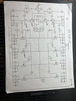
Problem channel and schematic used when built 2yrs so minus the diodes and 2nd pairs of mosfets.
Attachments
Last edited:
.032A, is 32mA, which seems extremely high. Can you double-check this? This would certainly point to a problem with the JFETs or their input connection. Remember a JFET without an input is effectively a short, or close enough.
I would use C3 and C4, in addition to small capacitors (around 470pF-1nF, whatever's in your junk box, if you have both, try the higher value first) across the 220R resistors. They are not shown in the schematic, but alluded to in the article as well as the guide. There's no footprint for those, far as I remember, so they can be tacked on to the resistor legs..
Bias drift is usually related to temperature differences between either input or output parts. If you spent a lot of time changing devices without results, maybe you should be looking at the source resistors. MOX usually have very, very high temperature coefficient and this is very good for high bias amps to proetct the output devices, but they can also be notoriously diffifcult to get matching for. Even the slightest drift, even from natural convection, can cause variation in your setpoint. You can verify this by blowing over the resistors to see the effect of this first hand.
Sangram I will check those values I’m assuming across R5 & R6? The .32a notes on the schematic was on there from the initial build when I was having some issues. I’ll recheck those values. I also have 1NF caps installed on the output boards. Are you saying to install caps across resistors R7-R10?
Also I was going to mention earlier it definitely seems to be temperature related because if I open a window because the F5’s heating up my dining room, or lift off the lid, I can notice changes.
Also I was going to mention earlier it definitely seems to be temperature related because if I open a window because the F5’s heating up my dining room, or lift off the lid, I can notice changes.
You said .32 in the above post, the notes on the schematic say .032A. Are you reading voltage, or current?
Current cannot be measured at that point, it has to be extrapolated from the voltage reading across the 10 ohm JFET source resistors in the input stage. Seeing the confidence of the schematic notes, I assumed this is what you did. Measuring the voltage at the point you noted is pointless as we do not know the resistance value, unless you measure that (with the amp off) and then divide the voltage reading (with the amp on) by it.
With P3 at mid position, the source resistor is 9 ohms and much easier to extrapolate current from. Usually 6-8mA is what you are looking for, so about 50 to 70mV.
A single cap across each of the two feedback chains is sufficient.
Current cannot be measured at that point, it has to be extrapolated from the voltage reading across the 10 ohm JFET source resistors in the input stage. Seeing the confidence of the schematic notes, I assumed this is what you did. Measuring the voltage at the point you noted is pointless as we do not know the resistance value, unless you measure that (with the amp off) and then divide the voltage reading (with the amp on) by it.
With P3 at mid position, the source resistor is 9 ohms and much easier to extrapolate current from. Usually 6-8mA is what you are looking for, so about 50 to 70mV.
I also have 1NF caps installed on the output boards. Are you saying to install caps across resistors R7-R10?
A single cap across each of the two feedback chains is sufficient.

that being R7 and R10A single cap across each of the two feedback chains is sufficient.
Ok, thank you. So I’ve done some checks.
Across:
R5 4.39v resistance amp off .589k/7.45ma calculated
R6 4.7v resistance amp off .581k/8ma calculated
R3 64.4mv
R4 69.5mv
whats storage is the resistance has remained constant at .589 across R5 but R6’s value is still dropping.
I’m going to have to pick up some caps to throw across R7 & R10
Across:
R5 4.39v resistance amp off .589k/7.45ma calculated
R6 4.7v resistance amp off .581k/8ma calculated
R3 64.4mv
R4 69.5mv
whats storage is the resistance has remained constant at .589 across R5 but R6’s value is still dropping.
I’m going to have to pick up some caps to throw across R7 & R10
Update on my power supply issues.
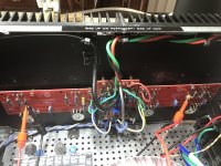
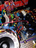
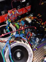
I have installed a second 400va transformer in the chassis and I am using each transformer to power the different rails. Photos attached.
So far so good, I have 34.9vdc negative on the negative rail and 34.9vdc positive on the positive rail. P1 and P2 are dialed to 0 ohms in preparation for biasing the amp. So far there is no mechanical noise coming from either transformer. I had to make a little junction board in order to connect all the power leads for the transformers.
When you buy the 5U chassis, you think you'll never fill it. Think again. It's getting crowded in here.
Attachments

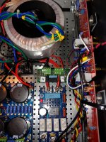
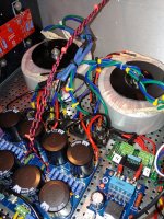
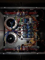
As you can see each secondary output from each transformer feeds it's own bridge rectifier (2 for each transformer). Then each of the secondaries are fed in parallel to the corresponding rail on the PSU board. This allows each rail to get the 24vdc input with the full 400VA from each transformer. The PSU board then converts the output up to 35vdc positive and negative at the output of the PSU to feed the channels of the amplifier.
Very nice, with the 800VA now getting into proper class-A territory.
Also, slightly better space utilisation in the case with two smaller torroids than a single bigger one!
Also, slightly better space utilisation in the case with two smaller torroids than a single bigger one!
Last edited:
I've biased this amp up so often over the last 6 or 7 weeks as I've worked through my transformer issues I can probably do it blind folded.
Just an observation the resistance of P1 and P2 is usually between 420 ohms and 450 ohms when fully biased up. At least that's what I've measured on the pots each time I reset them to 0 ohms for re-biasing after a power supply change.
Now I'm still running the amp with the diodes in place so I won't go over 350mv on the output devices. I believe that after 400mv the diodes come on and start to conduct.
Theoretically if I remove the diodes from the circuit I could bias up to 600mv which would be exciting indeed.... 😎 I certainly have the VA available
I've measured no higher the 43 degrees celsius over a sustained period at 350mv. I bought one of those laser thermometers specifically to record this while building this amp.
My standby amp was a BA-3 running 35v / 40w per channel which never got more than 44 degrees celsius in the 4u chassis. I had to remove that transformer from that amp to get the second transformer for the Turbo and I replaced the BA-3 with a standard F5 (I had the boards and the parts) and it measures no warmer than 42 degrees celsius in the 4u chassis and I have the bias set at 600mv on that amp.
My standby amp was a BA-3 running 35v / 40w per channel which never got more than 44 degrees celsius in the 4u chassis. I had to remove that transformer from that amp to get the second transformer for the Turbo and I replaced the BA-3 with a standard F5 (I had the boards and the parts) and it measures no warmer than 42 degrees celsius in the 4u chassis and I have the bias set at 600mv on that amp.
You could double the PSU as well and use one per channel. Put the 2nd one on top of the other, looks like there is enough hight available.
With dual secondaries per toroid, you could get a dual mono setup and double the filtration for even better bass response.
Looking very nice!
With dual secondaries per toroid, you could get a dual mono setup and double the filtration for even better bass response.
Looking very nice!
Last edited:
- Home
- Amplifiers
- Pass Labs
- F5Turbo Illustrated Build Guide