You need a decent amount of bias for the circuit to sound good, so you don't want to go below say 75% of target, but the higher rails are also good... your suggested voltage of a little below 40 will be fine.
Don't install the 'turbo' diodes, the circuit is a lot more reliable with them omitted.
Don't install the 'turbo' diodes, the circuit is a lot more reliable with them omitted.
Hello! I am SO sorry if this has been asked a zillion times already...but we are on 81 daunting pages....
What's wrong with reading 81 pages?
Thea answer is totally and fully dependant on your speakers and your personal listening levels in your room. Goal is to keep the amp in class A at all your listening levels.Hello! I am SO sorry if this has been asked a zillion times already...but we are on 81 daunting pages....
I will be building a stereo F5T which will be converted to monoblock when future funding permits a second set of parts. So, I'll go ahead and install the cascode in the FE. The boards and FETs have been ordered. Time for the power tranny. There are many options when it comes to rail VDC. My question is, is it sonically better to run a quite-high rail voltage and keep the bias current low? Or is it sonically better just to bump up the rail voltage slightly (36-40VDC) and keep the mosfets biased high? I want that classic full Class A sound and will be heatsinking appropriately either way. Thanks!
Thank you all!
I'm filling my Mouser cart. What are the recommended Q7 & 8 (cascodes) du jour? Papa's article says they really aren't critical so I'm inclined to get the trusty old TIP-29 & 32. Any better suggestions?
BTW, I found a second set of F5 transistors so I'll be jumping right to monoblocks. I've wanted a pair of Aleph 2s ever since the original Stereophile review all those years ago. I am hoping this build will satisfy that itch!

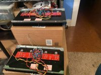
Hi-I finished my F5T. With 28V DC I have about 65W into 6 Ohm on my monoblocks. Please see attached pictures.
Great help from 6L6!!!! Thank you 6L6 a lot.
Still waiting for the front “half-moon shape” brass pieces, but it is cosmetics…
It is sounding very good to me. I tried to adjust P3 to min distortion and I used some local audio repair shop since I do not have distortion or spectrum analyzer.
My Bias is set to 1A (470mV) and MOSFETs are Toshiba 2SJ201 / 2SK1530.
Where did you source the panel mount bias indicator?
Thanks,
Wes
Ooo. I remember I purchased these from eBay (China), but it was long-long time ago and I have no records of that invoice in my purchasing archive. However, I do see these in Ali now: https://www.aliexpress.us/item/2255800981700017.html?gatewayAdapt=glo2usa4itemAdapt&_randl_shipto=US
How many pairs are you planning? I'm using 4 pairs per side at 44 volts. Massive heatsinks needed.
Whom are you asking?How many pairs are you planning? I'm using 4 pairs per side at 44 volts. Massive heatsinks needed.
So it’s been about a year since I finished my monoblock f5tv3 (Not balanced). They are the only amps I have been using, have performed absolutely flawlessly, and personally I Think they are the best amps you can build in the diy Pass arsenal (I built/own a few). I use a 625va 35v transformer with 63v 18k caps using diy audio store power pcb. My rail voltage is about 47v with about 350mv across source resistors. heat sinks about 52deg. I would like to squeeze out some more wattage. I read 6L6’s note where he said that Nelson swayed him against 65v rails but I’m not going that high and that was very early in thread before idea of no-diodes was mentioned.(I do not use the diodes). i would like to ask the collective intelligentsia two questions. Can I simply replace the transformer with 1000va 40v secondary for an extra 40-50w power with no other hardware changes? i would use fans to help compensate for reduced bias to try and keep it close to where it is now. I calculate the cascoded jfets would see about 18v with the existing 10k/4.75k resistors so don’t think anything needs to be adjusted here. The 63v power cap rating gets a bit close to calculated 56-57v rails that I should get with trafo change, but this should still be ok I think. Can this change be safely done? Second question is there has been some discussion of Antek not rating their trafos according to industry standards. Does this mean that for US 120v application the secondary voltage tends to run higher than stated or lower? Thank you all. Alex
The DIY store is currently out of F5T Mosfet kits. They do have the F5 kits. I do not plan on using the diodes in my build. The Tip31 and 32's are easy to get. I know we need to match the N and P mosfets that are sharing the same load ( parallel Fets). If I buy two F5 kits are all the N and P power Fets going to be matched per kit? If so I will just order two F5 kits as they are currently in stock. Other wise I will wait.


@Eslheadphone train your soldering - when you solder from below, the solder should flow through the hole plating to the other side and cover the pad there as well. Heat up the plated hole and component feet first and then apply the solder itself (to the plating and not the iron tip itself).
Has anyone tried powering up the amp without the power transistors or diodes installed. I would think we would be able to monitor the VGS while turning P1 and P2. This would also allow us to check the cascode voltage at the base of Q7 and Q8 . We could put current limiting resistors in series with the supply rails. Just thinking this would be a cool operational check before installing the output transistors.
I biased up and welcomed a new F5Tubo V2 to the world this morning.
It took a long time to build, but I was pacing myself. A step here, a step there, order some overlooked parts, call it quits of an evening. It's not a complex build, but there's a lot to consider and reconsider and research from this thread as time has gone by, parts have changed, approaches have settled in, others have been there, done that. Thank goodness for the Search tool!
It's the usual configuration: 5U deluxe case, Antek 6224 transformer yielding ~35v rails, cascoded, no turbo diodes, and replacing R5, R6 1k with 2.2k resistors to help biasing.
I'll put the covers and feet on it to bring it downstairs and give it a few days in the main room, letting it burn in hear what it does. My initial listening in my home office / electronics assembly workshop this morning did show it to be more pronounced in the upper half, yet controlling the bass.
Until then, thanks for this build thread as a knowledge base of how to build it.
Attachments
No, that is not correct.
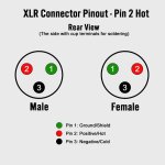
Edited to add... assuming you are building a balanced amp and that the XLR is wired per the norm.
Edited to add... assuming you are building a balanced amp and that the XLR is wired per the norm.
This could be a nice balanced mono block, but looks like a single ended stereo amp. Nice pic.Ment to post on this thread.
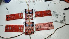
Boards are just about ready for installation. Note: P3 is in a socket Q1 and Q2 are wrapped in heat shrink for thermal bonding. The thermistor came from Mouser P/N 594NTCALUG02A472GA.
I can't understand what you mean,No, that is not correct.
Edited to add... assuming you are building a balanced amp and that the XLR is wired per the norm.
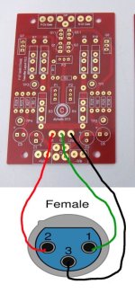
I use xlr inputs and wanted to know the sequence to follow in the pairings.
Pin 1 xlr is the ground
pin 2 xlr is the positive pole
pin 3 xlr is the negative pole.
On the gain stage board
In = positive pole
G = ground
Link = negative pole.
Is this correct?
Attachments
- Home
- Amplifiers
- Pass Labs
- F5Turbo Illustrated Build Guide