Hi Georg,
Just to confirm my order for 1 set of amp pcbs and 2 sets of Reg pcbs (one spare set).
Does anyone know of someone in a position to do 5 way matched sets of the 2013/313 Fets? I still have a 3 way matched set from the group buy, and would be interested in either a 4 way, or a full 5 way set - not in a position to do this myself, unfortunately.
Much appreciated GB - many thanks.
......what is the function of the 1uF cap with 1.5R resistor in series, on the PSU ?...
1R5 is there to decouple reactances of small bypass cap and big filter cap in order to avoid posible resonances.
+1
I'm also interested in a stereo set
Please send PM with your shipping and email address.
Thanks,
Georg
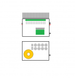
might build mono amps like this
each with seperate box for power supply
reg boards placed with power amp
power supply box with high current caps
multiple small lytics close to output board
or at least thats the plan right now 😛
my trafos are 400VA 2x 22V toroids
so the power supply box could also drive a turbo charged F5 😀
each with seperate box for power supply
reg boards placed with power amp
power supply box with high current caps
multiple small lytics close to output board
or at least thats the plan right now 😛
my trafos are 400VA 2x 22V toroids
so the power supply box could also drive a turbo charged F5 😀
Attachments
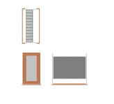
well, if noone else have anything, I guess it will be ok to post my revised box 'vision' 😛
Keep in mind that you will need considerable heatsinking for the regulators too.
For example: Secondary AC voltages of 2*22V will give you ~ 2*30V rectified DC. Regulated down to 2*20V means 2*10V*2A idle current ~ 40W dissipation per channel.
wow, thats like a small power amp
well, there would be plenty of space for the reg on bottom of my power amp main heat sink
measures like 300x250x70mm, each channel
sure hope they can take the heat then 😀
thanks
+/- 22V on amp rails ought to work ok, and give a bit less heat dissipation ?
with +/- 30 fed into the regs, what would be highest possible regulated output voltage ?
or what would be optimal operation voltage ?
wow, thats like a small power amp
well, there would be plenty of space for the reg on bottom of my power amp main heat sink
measures like 300x250x70mm, each channel
sure hope they can take the heat then 😀
thanks
+/- 22V on amp rails ought to work ok, and give a bit less heat dissipation ?
with +/- 30 fed into the regs, what would be highest possible regulated output voltage ?
or what would be optimal operation voltage ?
+-22V outputs should be possible.
That won't change your thermic balance however. Higher supply voltages will cause increased heating of the amp transistors.
Nevertheless, your heatsinks seem to be proper to manage that.

Last edited:
Nevertheless, your heatsinks seem to be proper to manage that
its really a full 1 meter from Fisher
too expencive, and stored for too long
due time to turn the heat on 😉
Hi Juma
Thanks for explaining the function of the series CR.
I have 4.7u polyesters...
...OK ?
Cheers.
Si.
Thanks for explaining the function of the series CR.
I have 4.7u polyesters...
...OK ?
Cheers.
Si.
If the voltage for the mosfets is +-22vdc can the source resistors then still be 0.33 ohm or do they need to be 0.68 ohm like in the schematic on the second page ?
Or has this more to do with the changed NFB in circuit 2 ?
Or has this more to do with the changed NFB in circuit 2 ?
Hi again Juma !
Another 'cappy' question...
In my 'cap stash' I have a whole-load of 40uF motor-runs...
...and 40x of the 4.7uF polyesters.
Would you consider it's worth using any of these ( get em' out the parts bin & juice em' ! )...
...and if so, where ?
The motor-runs were for a valve-project and / or mains filters...
...but I do have rather an excess !!!
( bit of a waste of voltage capacity...but people do, right ? )
Cheers.
Si.
In my 'cap stash' I have a whole-load of 40uF motor-runs...
Would you consider it's worth using any of these
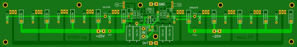
one connected at each output mosfet 😉
which is why I would have liked to have a power supply connection placed at each
basicly its just a few exstra holes for optional connectors 🙄
well, and maybe a few exstra ground points as well
Attachments
one connected at each output mosfet 😉
which is why I would have liked to have a power supply connection placed at each
basicly its just a few exstra holes for optional connectors 🙄
well, and maybe a few exstra ground points as well
OK, I added buffer caps to the boards (for example Nippon Chemicon super low ESR PXA series).
Central groundig point (0 V) is the load/buffer caps. So there are no extra terminals necessary at the amp boards.
Attachments
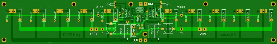
well, now we are at it 😀 and looking again, at your change, I wonder if a 'partly' groundplane would be possiblee
from ground connector, and going through like fingers between all mosfets ?
that way we could place a whole row of small caps, if we wish to
from ground connector, and going through like fingers between all mosfets ?
that way we could place a whole row of small caps, if we wish to
- Status
- Not open for further replies.
- Home
- Amplifiers
- Pass Labs
- F5 with 2SK2013/2SJ313