Measure the legs of the transistors to the heatsink to see if you have short or partial short. After that I would be looking with scope to see if there is any oscillations. What value gate stopper resistors do you have?
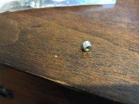
Promising discovery tonight. It appears that the screw insert that I installed in the aluminum heatsink to attach the problematic mosfet is slightly raised and not as flat as all the others. This means the hole I drilled was slightly too shallow. As a result, it doesn't seem like the mosfet is being push flat against the heatsink by the washer. I'm wondering if this could have an effect on the voltage, as I've observed that the tighter the washer, the lower the voltage across the source resistor. This is the first significant difference I've been able to find.
I'll report back tomorrow night after I fix that issue. Let's cross our fingers.
I'll report back tomorrow night after I fix that issue. Let's cross our fingers.
After years of lurking and maybe even some learning if I am not mistaken, the Mosfet will draw more current when getting hotter (which it WILL do if not properly snugged to the heatsink), i.e. "thermal runaway".
More proficient builders will chime in.
More proficient builders will chime in.
to eliasb1979 #22
Hello eliasb1979,
if one of your Mosfets isn't flat to the heatsink and thermal conduction is bad,
this can cause thermal runaway/drift.
If you have a infrared-thermometer you can check the temperatures of your Mosfets. 😉
Greets
Dirk
Hello eliasb1979,
if one of your Mosfets isn't flat to the heatsink and thermal conduction is bad,
this can cause thermal runaway/drift.
If you have a infrared-thermometer you can check the temperatures of your Mosfets. 😉
Greets
Dirk
Promising discovery tonight. It appears that the screw insert that I installed in the aluminum heatsink to attach the problematic mosfet is slightly raised and not as flat as all the others. This means the hole I drilled was slightly too shallow. As a result, it doesn't seem like the mosfet is being push flat against the heatsink by the washer. I'm wondering if this could have an effect on the voltage, as I've observed that the tighter the washer, the lower the voltage across the source resistor. This is the first significant difference I've been able to find.
I'll report back tomorrow night after I fix that issue. Let's cross our fingers.
Yes. That will have the effect of higher current.
Good news. After changing the source resistors upfront again and deepening the holes so the front two transistors were flatter, the current to the front mosfet is now almost equal to the back two. That was the problematic mosfet that was hogging the current.
The second mosfet is still about 25-30mv above the others, but I am going to try to change its source resistors one last time and see if that makes any difference. Otherwise, I might just live with it and bias the amp so that that the second mosfet is around 300mv.
For those that asked, I use the insert because I find it easier to just drill a hole and not worry about tapping it. You can always screw up the tapping, whereas the insert just pops in. I've used them on five amps without problem. It appears I just drilled a too shallow hole on this amp for some reason.
Not wanting to be nitpicking, but I honestly doubt you have a source resistor issue... That said I would be REALLY interested in what type of insert you have used...

You might be surprised about tapping being pretty easy. I use a Home Depot kit for 6/32 screws. I got the m3 size bits and taps recently for my singing bush build.
I use my cordless drill. The key I learned is use a squirt of wd40 as lubricant, and to take it slow. Tap until the resistance increases, back it off, wipe the swarf off the tap with a paper towel, dip the tap in the little wd40 puddle, tap again. Mosfet heat sink taps end up being 3 sips of the tap on average for me.
I ended up getting at 10 pack of the proper bits for 6/32 taps on Amazon - bench is a mess, so now I just reach for the packet.
Not a fan of those honestly, but use whatever you like. That said, just make sure your hole is deep enough to have the insert somewhat recessed in there and properly de-burr (?) the holes... should be fine..
So good news. After fiddling with how the front two mosfets were seated on the power sink and attached to the output boards, I as able to get them all balanced very well.
The voltage across each of the four source resistors is around .195, which results in the heat sink temperature stabilizing at around 51 degrees after three or four hours. I believe that works out to about 1.56 amps per n- and p-channel.
Is this an adequate amount of bias for this amp?
And BTW, the amp sounds and looks great!
Know I just need to add the speaker protection board to the other amp without screwing that one up 🙂
I think you have some headroom with the bias.... I would say it depends on the heat you are willing to tolerate.
I think 30W per FET is totally acceptable, but as always take my comments with a pinch of salt, I am a painting by numbers guy.
I think 30W per FET is totally acceptable, but as always take my comments with a pinch of salt, I am a painting by numbers guy.
Good news that it's working!!!
I remember when I built turbos for a friend the article said something about biasing up to 90% and running a while. We ended up leaving it at whatever that 90% point was. I can't recall the exact point, it's been a year and a half.
I remember when I built turbos for a friend the article said something about biasing up to 90% and running a while. We ended up leaving it at whatever that 90% point was. I can't recall the exact point, it's been a year and a half.
This is a V3 running at +/-50ish volts?So good news. After fiddling with how the front two mosfets were seated on the power sink and attached to the output boards, I as able to get them all balanced very well.
The voltage across each of the four source resistors is around .195, which results in the heat sink temperature stabilizing at around 51 degrees after three or four hours. I believe that works out to about 1.56 amps per n- and p-channel.
Is this an adequate amount of bias for this amp?
And BTW, the amp sounds and looks great!
Know I just need to add the speaker protection board to the other amp without screwing that one up 🙂
1.56A gives you around 38W class A at 8ohm load.
- Home
- Amplifiers
- Pass Labs
- F5 Turbo V3 - Help with uneven bias on N Channel