I'm building the full out V3 with 4pr.
So in the case of 4pr is there benefit of running wire directly to each connection hole of the output boards? or one wire split close to the boards to the gates and O/P at the output board be ok?
Also, what would be the best way to connect the speaker out when I have 4pr (2N and 2P boards ?)
Hi Dazed .🙂
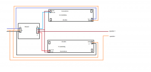
Check this out ,maybe it will help!
NS😀
Attachments

I noticed a big difference in V2 vs standard F5. I did not notice as big a difference with V3, but I think there is a simple explanation. V2 gave me all the power(headroom) my drivers needed or wanted and v3 really didn't add anything, other than DF. I would expect those who would see an improvement from V3 over V2 are those who need the extra power, like yourself. I clearly hit the ceiling in gain. THat being said. V2/V3 was a completely different animal than the F5. In your case, I would suggest multiple output pairs and less per fet bias. I am working on a f4 output board that could be easily converted to work as output to f5 Fe, if you are interested. NOt going to produce it, but I know you have a special need for power, due to your speakers. I currently have 6 pairs on the board spread out over about 16", using universal mounting spec.
Perhaps the biggest difference was due to the rail voltage? Whether you use a V3 or V2 is subtle, but the difference from a 20 volt rail to a 50 volt rail will not be.
What would your reasoning be? Greater voltage swing/dynamic headroom? Not arguing, just wondering/learning. Seems balance is way to go if you want voltage headroom. My v2/3 attempts used same rail voltage as standard F5.
Last edited:
Hi Dazed .🙂
Check this out ,maybe it will help!
NS😀
Perfect! That was the information i was waiting for. Winner!! 😀.

Thanks audio san
Hi Audio San🙂
Thanks for catching that I'll delete that one it's in the thread here somewhere,That's where I found it.
NS
no smoking. there is a foult on that one. N ch and P ch must be switched.
Hi Audio San🙂
Thanks for catching that I'll delete that one it's in the thread here somewhere,That's where I found it.
NS
What would your reasoning be? Greater voltage swing/dynamic headroom? Not arguing, just wondering/learning. Seems balance is way to go if you want voltage headroom. My v2/3 attempts used same rail voltage as standard F5.
I don't have the answers, just more questions...
Energy in the power supply is proportional to the square of the voltage. I've always found that the higher voltage rails sound more "effortless". Perhaps there is a relationship? Maybe rail voltage droop does not sound so severe when you start with a lot of voltage?
Sorry for the subjective...
I always assumed your F5T had higher voltages. Now I'm really excited to build it!
her is a correct one. but the conections on the outputs are not the same on the store boards. this was for the prototype boards.
So if I use 4 pr, so 2 output boards per N and P, would I just join them right at the gain stage board? or would I somehow connect them together?
Thanks!
F5t boards - Spacing of OT
Could someone kindly let me know the spacing between the output transistors on the official F5t boards ?
TIA,
Max
Could someone kindly let me know the spacing between the output transistors on the official F5t boards ?
TIA,
Max
Thanks a lot - it's not that I was too lazy to look for the information, but it did not come to mind to check the UMS...
Thanks a lot - it's not that I was too lazy to look for the information, but it did not come to mind to check the UMS...
It's not immediately obvious that the answer to your question is the UMS - that is why I thought the link would be useful. 😀 😀 😀
Are you building your own chassis / enclosure?
Just to confirm:
If I am going to build the F5T V3 (4 pairs of output FETs per channel)in the form of 2 monoblocks (4 output FETS on each heat sink), the boards from the store provides the most flexibility and I need 2 sets?
Thanks guys!
Regards,
If I am going to build the F5T V3 (4 pairs of output FETs per channel)in the form of 2 monoblocks (4 output FETS on each heat sink), the boards from the store provides the most flexibility and I need 2 sets?
Thanks guys!
Regards,
Are you building your own chassis / enclosure?
Yes, planning on V3 mono using 400x200mm heatsinks, 1000VA transformer, around 24mF , would need some help on rail-voltage vs. bias though...
Around 38V rails seems to be a good comprimise, leaving at least 1A per FET if aiming for roughly 40W per device, no ?
thats internal temp. I hope you have big sinks.
Sinks are given for something like 0.15 C/W, looks good to me - will have to do some calcs though
- Status
- Not open for further replies.
- Home
- Amplifiers
- Pass Labs
- F5 Turbo Circuit Boards