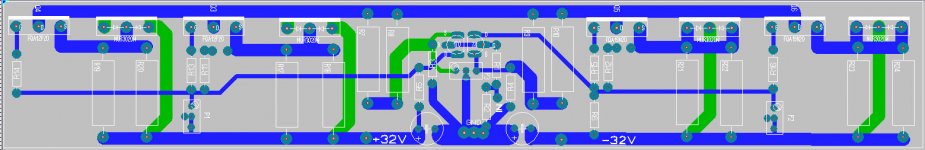
Here you go all checked..i think 🙂
Some minor changes as well with placing of thermistors.
This layout can easily me stretched both ways to optimize for your case size and distribute heat dissipation...but don't go to close to the edges!,
as is its 36mm x 221mm
Going to keep working on the rectangular lateral transistors version....just fold both ends of this one down...!.
Of course one might argue that the advantage of central input ( and hence only one PCB design times 2 ) is outweighed by the fact that input is not as far away from Trafo as possible....something to consider.
If the design was to mimic NP layout...input at the very end we would need left and right PCBs.
From my experience with PD pcbs F5 is dead silent and this is really a non-issue here.
Attachments
Gerbers out by CeeVee's request.
I managed to snag them before they got deleted. Now deleted from my hard disk pending their re-release (not that I could have used Gerbers anyway, need PDF files).
If some creative Far East Asians got them before they were removed, you will be able to see eBay copies pretty darn soon.
CeeVee
They say that imitation is the highest form of flattery....
Be flattered, be very flattered.
I have re-layed my board to your layout.
Slightly larger board and still retaining the Phoenix connectors.
Anybody interested in a Group Buy????
Andy
They say that imitation is the highest form of flattery....
Be flattered, be very flattered.
I have re-layed my board to your layout.
Slightly larger board and still retaining the Phoenix connectors.
An externally hosted image should be here but it was not working when we last tested it.
Anybody interested in a Group Buy????
Andy
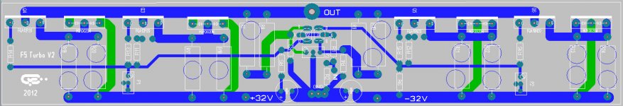
Is it my imagination, or is D4 not in the same mounting plane as the rest of the flat-pack devices?
Is it my imagination, or is D4 not in the same mounting plane as the rest of the flat-pack devices?
Well spotted 🙂
Making a quick mod.
I'll also add some addition pads for longer power resistors.
Is it my imagination, or is D4 not in the same mounting plane as the rest of the flat-pack devices?
OK. Should be sorted now.
An externally hosted image should be here but it was not working when we last tested it.
OK. Should be sorted now.
An externally hosted image should be here but it was not working when we last tested it.
got it

But you can still move R11 to the left of the Thermistor same for R12 to the right
Last edited:
got it
But you can still move R11 to the left of the Thermistor
Well......
I could but that would mean offsetting the thermistor from the centre of Q3 or moving the gate resistor. Don't you think the symmetry is 'pretty'??
Course is fine just a bit shorther tracks could shift R11 a bit like you did for R12
and R12 to other side of thermistor let you pick up voltagge from the mosfet is bolted 2.
But I am just being fussy get yourself a well deserwed pint
etch one proto and sleep over it
and R12 to other side of thermistor let you pick up voltagge from the mosfet is bolted 2.
But I am just being fussy get yourself a well deserwed pint
etch one proto and sleep over it
Course is fine just a bit shorther tracks could shift R11 a bit like you did for R12
and R12 to other side of thermistor let you pick up voltagge from the mosfet is bolted 2.
But I am just being fussy get yourself a well deserwed pint
etch one proto and sleep over it
OK, How's this
An externally hosted image should be here but it was not working when we last tested it.
I think I'll trim off the waste board on each size. Should make manufacture a little cheaper. Even with the thickness of the tracks as they are I think I might go for 2oz board. Do you think 1.6mm board is thick enough or shall I go for 2mm?
Be sure and ask for Papa's blessing, silk screen diy clone pass design on board, plus we don't mind if you make money. this is a hobby not a profession . Mr Pass(AKA Papa) is very generous with his Ideas and help. We would like to keep it that way.
Old guy in SC, Elwood
Old guy in SC, Elwood
No no.
You're right, this is a hobby.
If I do make a batch (only with NP's blessing of course) then I will sell at my cost plus a couple of dollars per set as a donation to the forum.
I have already put attribution on the silk screen.
Regards
Andy
Old guy in London, England 🙂
You're right, this is a hobby.
If I do make a batch (only with NP's blessing of course) then I will sell at my cost plus a couple of dollars per set as a donation to the forum.
I have already put attribution on the silk screen.
Regards
Andy
Old guy in London, England 🙂
- Status
- Not open for further replies.
- Home
- Amplifiers
- Pass Labs
- F5 Turbo Circuit Boards