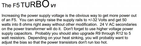
The modelling is simple.
If you have an existing build that uses +-24Vdc supplies and the total output bias is 1.8A, then the dissipation is P= IV = 1.8A*{24+24V} = 86.4W
You want to predict the operating condition for a new build where the dissipation and the heatsink temperature remain the same.
Inew = P/V = 86.4W/{32+32} = 1.35A
Thank you Andrew. That math is helpful.
So, with the 5U case and 24V rails and 2.4A bias Iam dissipating 115W.
Same dissipation with 32V rails equals 1.8A bias.
This is what I'm considering when it is available:
https://linearaudio.nl/la-autoranger
https://linearaudio.nl/la-autoranger
I am glad you recognised the risk of damage and stopped to ask.
You need an attenuator between the high level output and the sound card input.
That attenuator could be a simple vol pot but that makes it difficult and time consuming to use.
Better would be a fixed attenuator with a known convenient level reduction.
A stepped attenuator would be better. Steps of /1, /2, /4, /10 would be a start. Or in dB if you prefer.
In addition an overload filter would be a useful. This can be as simple as a pair of diodes that act like a shunt regulator, to limit the voltage sent to the SC input.
There are a few designs linked from this Forum. Did Millet do one?
Seems suitable!!
1.8A of total Bias in a push pull amplifier gives a maximum ClassA output of nearly 3.6Apk.Thank you Andrew. That math is helpful.
So, with the 5U case and 24V rails and 2.4A bias Iam dissipating 115W.
Same dissipation with 32V rails equals 1.8A bias.
That is equivalent to 51W into 8ohms.
pcb?? F5 turbo
Hi, can anyone help me? I would like to make my Aleph F5 turbo ... someone to, can i provide the files (gerber ??) x the PCb ?? thank you🙂
Hi, can anyone help me? I would like to make my Aleph F5 turbo ... someone to, can i provide the files (gerber ??) x the PCb ?? thank you🙂
PSU wiring scheme
Hello Nelson, hello all,
With a friend we are building a F5T_V2 in mono blocs 😛
I have a question about PSU wiring. I'm not so familiar with F5T_V2 psu, which is said to be robust, beefier. Here it is:
On regular (older) Firswatt PSU, diode bridges are in series between rails :
Thus 2x more voltage drop I guess ? And no connection for ground to secondaries of the toroid. Each polarity is rectified separately
On F5 designs I noticed that scheme with ground connection at secondaries was used; on the contrary, on Aleph J PSU schematic, no connection ...
If I put diode bridges in parallel is it OK ? like in this pic :
And is it the same scheme as in first pic of my message ? Clarification about diodes wiring would be great 😎
Thanks !
Best,
nAr
Hello Nelson, hello all,
With a friend we are building a F5T_V2 in mono blocs 😛
I have a question about PSU wiring. I'm not so familiar with F5T_V2 psu, which is said to be robust, beefier. Here it is:
An externally hosted image should be here but it was not working when we last tested it.
On regular (older) Firswatt PSU, diode bridges are in series between rails :
An externally hosted image should be here but it was not working when we last tested it.
Thus 2x more voltage drop I guess ? And no connection for ground to secondaries of the toroid. Each polarity is rectified separately
On F5 designs I noticed that scheme with ground connection at secondaries was used; on the contrary, on Aleph J PSU schematic, no connection ...
If I put diode bridges in parallel is it OK ? like in this pic :
An externally hosted image should be here but it was not working when we last tested it.
And is it the same scheme as in first pic of my message ? Clarification about diodes wiring would be great 😎
Thanks !
Best,
nAr
Last edited:
The top diagram uses a centre tapped transformer secondary and uses a single bridge rectifier, with each diode duplicated to increase the current capacity.
The middle diagram shows a dual secondary transformer with a dual bridge rectifier.
You should not confuse these as they are not swappable.
The lowest diagram is a waste of diodes. I think that you have copied the top diagram, but I would only start this up as a PSU alone via a Mains Bulb Tester and thoroughly check the voltages are as expected.
The double bridge was part of the design goal of getting more watts from a given power supply. Along with the diodes across the source resistors the parallel bridges help to squeeze out maximum power. For real world loads of 4-8 ohms you might be able to measure the difference between 1 and 2 bridges but it would be very difficult to hear.
hi guys, just a quick question, for f5 turbo v2, should I need to use soft starter for inrush current (400 VA transformer) ?
and also should I consider speaker protection boards?
and also should I consider speaker protection boards?
Hi,
try using a close rated mains fuse.
For a 400VA 230Vac transformer you should be using a T2A mains fuse.
It will rupture when you switch ON.
That repeated rupturing of the correct mains fuse tells you your transformer needs a soft start.
Try it.
After setting up your soft start you may find that you can use a T1.6A fuse.
I have 10A fast blow mil spec silver fuse (russian fuses) . is that too much for this job? (actually I am using this fuse on a class d amp 🙂)
Hi,
try using a close rated mains fuse.
For a 400VA 230Vac transformer you should be using a T2A mains fuse.
It will rupture when you switch ON.
That repeated rupturing of the correct mains fuse tells you your transformer needs a soft start.
Or you use a slo-blo 2a fuse. 😉
Andy
10A on a 230Vac mains supply is for 2300watts of power.I have 10A fast blow mil spec silver fuse (russian fuses) . is that too much for this job? (actually I am using this fuse on a class d amp 🙂)
You said you have a 400VA transformer.
The fuse will have T or F stamped on it.Or you use a slo-blo 2a fuse. 😉
Andy
T2A for time delayed, or F2A for fast rupture.
I have never seen a fuse with slo, or S2A on it.
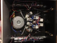
I just changed my 24V rail/dual pair Toshiba Mosfet to 32V rails with no cascode. I also updated the feedback arrangement from the original F5 values to the decreased feedback F5T arrangement. I also deleted the current limiting.
I had to decrease bias from 2.4A to 1.7A due to the rail voltage increase. I am using the 5U chassis.
It now has more headroom and gain. Pretty obvious. But I think I may prefer the sound of 24V rails and higher bias. Not sure yet. It sounds more different than I expected. It sounds lighter and slower than the 24V rail version but it can go a little louder. Not sure if it's worth it. I am sure this is due to the bias decrease and less feedback.
I am going to live with it for a while and see. Is it wise to use the original F5 feedback arrangement with 32V rails and dual pairs? Or is will the amp become unstable?
Attachments
I have seen many commercial amps with 400 va transformers that do not have any soft start. I recently built an Aleph j with a 400va Antek transformer. I did not use any soft start and there are no issues. I am running a CLC supply filter and the first capacitor is somewhat smaller than what most supplies use. I use a slow blow fuse of 3 amps and they seem to last so far.
That said, not all toroids are designed the same way. Some will draw higher peak currents during startup and are more likely to complain when started up into a rectifier circuit with a large filter capacitance. If you hear a significant hum or buzz or Gronging sound during startup that's a good clue that you will need some soft start cushioning.
That said, not all toroids are designed the same way. Some will draw higher peak currents during startup and are more likely to complain when started up into a rectifier circuit with a large filter capacitance. If you hear a significant hum or buzz or Gronging sound during startup that's a good clue that you will need some soft start cushioning.
The fuse will have T or F stamped on it.
T2A for time delayed, or F2A for fast rupture.
Correct. 🙂
T2A for time delayed, or F2A for fast rupture.
I have never seen a fuse with slo, or S2A on it.
'Slo blo' is the common-use name for a time delayed fuse.
Andy
After living with the F5T v1 (dual pair mosfet) for a week I have to say I think I prefer the original F5 feedback arrangement. Has more drive and pop. The extra headroom w/32V rails is nice however.
Nelson says the decrease in feedback and increase in gain in the Turbo effects stability. Anyone had problems using the original F5 feedback arrangement (4x100R) with 32V rails and dual pairs mosfets?
Nelson says the decrease in feedback and increase in gain in the Turbo effects stability. Anyone had problems using the original F5 feedback arrangement (4x100R) with 32V rails and dual pairs mosfets?
The feedback arrangement is the same.After living with the F5T v1 (dual pair mosfet) for a week I have to say I think I prefer the original F5 feedback arrangement. Has more drive and pop. The extra headroom w/32V rails is nice however.
Nelson says the decrease in feedback and increase in gain in the Turbo effects stability. Anyone had problems using the original F5 feedback arrangement (4x100R) with 32V rails and dual pairs mosfets?
The values used in the feedback can be changed and yet retain the same gain.
You need to be aware that lower values will give higher resistor temperatures and these temperatures will give rise to distortions. There can be distortions due to voltage coefficient.
One can also change the gain. That does affect the stability margins.
It is generally the case that increasing the gain decreases the feedback and increases the stability margins.
Going the other way. Decreasing the gain and increasing the feedback usually decreases the stability margins and this is usually audible as the HF amplification becomes higher than the passband amplification. The transients appear to be enhanced.
Test your modifications thoroughly to avoid this problem. Don't inadvertantly create ringing of fast transients because you have not fully "designed" your changes.
Last edited:
- Home
- Amplifiers
- Pass Labs
- F5 Turbo Builders Thread