So from what I have been reading most people are saying you need more than 4 pairs for 100w or greater. The paper Pass put together says that 4 pair for 100w can work. I have very large heatsinks from an industrial drive. They are 24"x9"x3" depth fins. In fact I'm planning on a stereo chassis with 2 of these heatsinks and a common 2kVA transformer. The transformer will be outboard with umbilical connection to electronics on the heatsink. Am I crazy??
So from what I have been reading most people are saying you need more than 4 pairs for 100w or greater. The paper Pass put together says that 4 pair for 100w can work. I have very large heatsinks from an industrial drive. They are 24"x9"x3" depth fins. In fact I'm planning on a stereo chassis with 2 of these heatsinks and a common 2kVA transformer. The transformer will be outboard with umbilical connection to electronics on the heatsink. Am I crazy??
Outside transformer is not good if you want good basstransients.
The dc conversion and dc caps will be located in the section with the amplifier boards. Connecting the xfmr with low gauge cables I would think should take care of any weak bass issues. There are examples of this particularly in the tube field.
Pass Xs amps do this and there doesn't seem to be a problem. I would however preform dc conversion and smoothing in the transformer case and then have a second capacitor bank near the amplifiers PCB.
Last edited:
4 pairs will be fine for 100W. Heatsinking is the issue.
I run 4 pairs per side pushing 150W at 8ohm with no issue. However I do it with double the heatsink that you listed and I only get a 15-17C rise above ambient at the heatsink.
If you want to take the transformer away from the main chassis, thats fine, I would rectifiy it in that separate chassis, and as MASantos says, add a second smaller cap bank at the main amplifier chassis.
The dc conversion and dc caps will be located in the section with the amplifier boards. Connecting the xfmr with low gauge cables I would think should take care of any weak bass issues. There are examples of this particularly in the tube field.
Tubes can not control anything at. Not evven 600 W amplifiers costing a million.
Outside transformer is not good if you want good basstransients.
If there is another capacitor bank in amp chassis then cable merely acts as R in CRC.
AC output impedance of powersupply should still be ok.
I don't see it as a show-stopper there's always an alternative route to nirvana.
10mV of delta Vgs is a fairly good standard.All transistors from same lots matched VGS at 200ma to .01. that should be good should it not?
That makes me wonder if you fitted good source resistors or good thermal conductors?
I don't agree with the philosophy of locating the transformer in a remote chassis.Outside transformer is not good if you want good basstransients.
But that does not lead to bad performance for bass transients.
The dc conversion and dc caps will be located in the section with the amplifier boards. Connecting the xfmr with low gauge cables I would think should take care of any weak bass issues. There are examples of this particularly in the tube field.
Fit adequate supply rail decoupling for all the medium and high frequency transients.
Fit local second stage smoothing capacitance in the amplifier Chassis.
Do all the rectifying and rough smoothing in the transformer Chassis.
and just to prove my point
Dazed and 2pico also agree !Pass Xs amps do this and there doesn't seem to be a problem. I would however preform dc conversion and smoothing in the transformer case and then have a second capacitor bank near the amplifiers PCB.
Erland,
where did you get your information?
Last edited:
Go advanced
Manage attachments
browse your PC to locate the file
upload
close this window.
I find it easier if I save the cropped and resized pic to desktop. Select a sensible resize to suit the detail you want us to see.
Then we have the pic for as long a DIYaudio exists.
And it downloads in Thumbnail.
Manage attachments
browse your PC to locate the file
upload
close this window.
I find it easier if I save the cropped and resized pic to desktop. Select a sensible resize to suit the detail you want us to see.
Then we have the pic for as long a DIYaudio exists.
And it downloads in Thumbnail.
Last edited:
I thought that is what I did. How do I get to advanced? Do you mean use "post reply" instead of quick reply? I used post reply and went to attachments browsed for the file and uploaded.
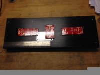
So take a look at my heatsink Dazed2. Yours is twice as big as this with 4 outputs on it. I thought mine would be plenty big! Maybe I'm wrong.
You should be fine as long as you don't plan to drive 2 ohm loads. However if you do, just stick a few fans on the bottom and you'll be good.
10mV of delta Vgs is a fairly good standard.
That makes me wonder if you fitted good source resistors or good thermal conductors?
I used the same source resistor for each device tested and attached it to the same heatsink in the pic I provided. I then measured VGS at start of the test at 60 sec and 120sec.
OK I am bench testing a single channel. Everything going well no issues that I know of yet. A V3 model +/- 45vdc under load. I am trying to understand biasing this thing. I am biased at .3300vdc measured across a single source resistor of 1R0. There are 2 resistors in parrallel for .5 ohm per transistor. So that means I am running at .66amp per transistor. Isn't each transistor supposed to be biased at around 1 amp each? But I also am reading in forum it should be around .3-.4vdc across each source resistor. That doesnt add up to 1-1.2 amp per resistor either. Someone help explain the bias please. BTW heatsink temp at 118 deg.F after 2 hours and Bias holding steady.
118°F = 47.7°C
that leaves you with a bit of temperature to spare.
Reduce the bias voltage back to zero.
Add a third 1r0 to your existing to make 0r333
Now increase your bias towards 0.333Vrs checking your temperatures after a period of heatsoak.
The F5 and variants are a Push Pull design and does not current clip when it tries to leave ClassA. It just transitions into ClassAB.
If you set your bias to 1A then your F5t will have a maximum ClassA output of 2Apk for each output pair.
i.e. a 2pr will have a maximum ClassA output of 4Apk, a 3pr 6Apk.
When your load (speaker) demands more current the f5t just goes into ClassAB to meet that demand.
- Home
- Amplifiers
- Pass Labs
- F5 Turbo Builders Thread