In the F5T article NP says that diodes conduct at between .3 and .6v depending on temperature - hotter meaning lower - also I would be planning on 4 ohm loads so they would seem to be likely to do _something_ in that scenario.. albeit further into the conduction of the output devices than with the F5Tv2. Whether that something involves letting smoke out of things or making a horrible distortion or do something useful is beyond my feeble newb reckoning.. 😕 I don't even know really how to sensibly choose between the DOGC-H and F5T v2, other than I have a chassis with two toroids in already that will do for either (big with +-36vdc rails on caps) but included heatsinks are a bit wimpy (pretty chunky but very short fins) for the F5Tv2. That and my friend has a quad 606 that I like the sound of.. so this current dumping/error correcting feed forward stuff with low heat is appealing.. that and that the output devices don't need matching. Downside seems that not too much build info is about on the DOGC-H in English.. and there's buttloads for the F5 variants from all kinds of helpful people and it seems sonically very well regarded.
Last edited:
I´m gathering the parts for F5 Turbo, according to NP, resistors R9-R12 should be 5 Watt. What´s confusing me is that R9 and R10 is originally 1/4 Watt and R11 and R12 3 watt. Should they all be 5 Watt or am I missing something?
What schematic are you referring? In the F5T article by Nelson Pass the original F5 contains R9-R12 marked at 3W.... is that R9 and R10 is originally 1/4 Watt and R11 and R12 3 watt ...
Resistors: (All are 1/4W unless otherwise specified)
R1 – 10R / 1W
R2 – 10R / 1W
R3 – 2.2K
R4 – 2.2K
R5 – 100R / 3W
R6 – 100R / 3W
R7 – 100R / 3W
R8 – 100R / 3W
R9 – 4.75K
R10 – 47.5K
R11 – 0.47R / 3W
R12 – 0.47R / 3W
This is from the partslist, I read it as R9 and R10 is 1/4 Watt. I understand that they logically should be 3 Watts, but it´s confusing to read: Resistors: (All are 1/4W unless otherwise specified)
Setting F5T v2 bias.
I am likely to miss something here - have nearly completed 1 ch of v2 with 2 OP pairs and with the diodes, 2 source resistors per FET (2 x 1 Ohm), rail V is about 34V. Tried to bias it yesterday, and was able to reach 0.555V (while did not ran out of steam on the multiturn pot). Sinks feel like ~50C (pretty hot, but can keep my hand on it indefinitely - that's after about an hour or more of running the amp).
The bias seems to be stable at that point (ambient ~20-21C).
Question - is not this V value a bit high (I expected bias to start running away in 0.350 - 0.4V interval)?
Hmm... definitely not DVM (have 3 of them, all the same). Diodes - could it be all 4 (or, it can misbehave even if one is off)? Likely something wrong with PCB - or what it has become, khe-khe, after I've modded the nice Tea-bags boards 🙂))
Doolav, it´s this guide I´m using: www.diyaudio.com/.../build-guides/diyaudio-f5-b...
https://www.google.se/?gws_rd=ssl#
https://www.google.se/?gws_rd=ssl#
Hmm... definitely not DVM (have 3 of them, all the same). Diodes - could it be all 4 (or, it can misbehave even if one is off)? Likely something wrong with PCB - or what it has become, khe-khe, after I've modded the nice Tea-bags boards 🙂))
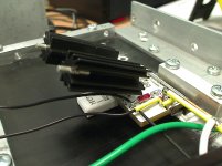
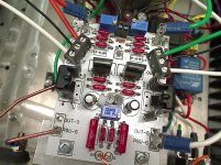
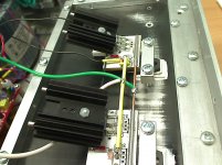
give us some pictures
Doolav, it´s this guide I´m using: www.diyaudio.com/.../build-guides/diyaudio-f5-b...
https://www.google.se/?gws_rd=ssl#
link is ooked , completely

bearwik, I guess you are talking about this: http://www.diyaudio.com/forums/diyaudio-store/227933-diyaudio-f5-build-guide.html
then it does not match the one in the F5T article, hence different values.
Link <---> article
R1 – R3
R2 – R4
R3 – R5
R4 – R6
R5 – R9
R6 – R10
R7 – R11
R8 – R12
R9 – R1 (not exactly)
R10 – R2
R11 – R7
R12 – R8
etc.
If you are targeting F5T, stick to the schematic in the article - that will allow easier transition from F5 to F5T, and it's more up to date.
bearwik, I guess you are talking about this: diyAudio F5 Build Guide
then it does not match the one in the F5T article, hence different values.
Link <---> article
This is what the F5 Turbo article says: Probably you should also upgrade R9 through R12 to 5watt resistors
I read that as I can use the original F5 build guide and just upgrade R9-R12.
That alone will not convert f5 into turbo version. Depending on your load demand you may need to raise rail voltage or bias or both.
[That alone will not convert f5 into turbo version./QUOTE]
I know that, I got a 500 Va 24 volt trafo and 63 volt capacitors. Can I use the original partslist if I change R9-R12?
- sounds like a plan for F5T v2.500 Va 24 volt trafo and 63 volt capacitors
- if you also change source resistors, this will bring you to F5T v1.Can I use the original partslist if I change R9-R12
Source resistors are R7-R8 in the original 'F5 AMPLIFIER' schematic in the article above. They become R17-R24 in the 'F5 TURBO V1' schematic in the same article.
- Home
- Amplifiers
- Pass Labs
- F5 Turbo Builders Thread