Don't worry about it...
Use whatever you can get easily - they are source resistors, and low value, so any Johnson noise will be essentially unmeasurable, and completely inaudible.
Use whatever you can get easily - they are source resistors, and low value, so any Johnson noise will be essentially unmeasurable, and completely inaudible.
Don't worry about it...
Use whatever you can get easily - they are source resistors, and low value, so any Johnson noise will be essentially unmeasurable, and completely inaudible.
Thanks Jim. I think I recall reading Mr. Pass saying that the source resistors have an effect on the sound with verticals. Maybe I am completely wrong.
Since you are a "serial" amp builder what would be your number 1 choice for source and feedback resistors?
BTW really appreciate all your work on this forum. Thank you.
Nash
Panasonic ERX or ERJ.
Which, not coincidentally, are the ones in the factory Pass and Firstwatt amps...
🙂
Which, not coincidentally, are the ones in the factory Pass and Firstwatt amps...
🙂
Panasonic ERX or ERJ.
Which, not coincidentally, are the ones in the factory Pass and Firstwatt amps...
🙂
Thank you.
If I have an F5, F5Tv2 and v3, will they have the same voltage gain? I want to build a couple for my LxMini's, but I need the gain to be identical. The F5, or F5Tv2 would be fore the full range drivers and the F5tv2 or v3 would be fore the woofers.
No. The F5 has less gain due to higher amounts of feedback.
The V2 and V3 have higher gain due to feedback amounts and rail voltages.
Change the feedback resistors on the F5 to 220ohm and stick a 25K pot on front of the turbos, that should work really well.
The V2 and V3 have higher gain due to feedback amounts and rail voltages.
Change the feedback resistors on the F5 to 220ohm and stick a 25K pot on front of the turbos, that should work really well.
The ratio of the feedback resistors sets the gain (voltage gain)
The supply voltage and/or the number of devices used in the output has nothing to do with gain.
If you require the same gain from all the different versions of the F5/F5t then just set the NFB ratios to the same value.
If these need to be close, then +-1% tolerance gives a range of gain from +15.39dB to +15.73dB
You are likely to find that none of your gains will be at these extremes. Expect a maximum deviation of ~ ¼ of that range i.e. <0.1dB difference.
If you require extreme accuracy in gain then start matching resistors to better than +-1%
Must the input RCA be shielded? I have a twisted pair of 20 awg running between the power and ground en-route to the input on the FE board. It is all of 1" long.
who said it had to be shielded?
A UTP (unshielded twisted pair) is just fine.
Or STP or Coaxial.
A UTP (unshielded twisted pair) is just fine.
Or STP or Coaxial.
All of your options end up with a shared Zero Volts.
This makes your 3 box amplifier the same as any other multichannel amplifier.
YOU have to decide where to connect the Main Audio Ground of the two amplifiers such that you don't end up with a Loop in your signal return circuits.
I built it in one box, and am having trouble with the loop in the signal return circuits. The power delivery architecture uses the output boards as the power bus with the FE board at the very end. Grounds are taken from both N and P channels to the FE boards. The safety earth from the IEC is attached to the chassis.
The power supply boards are the Tea Bag boards, and are wired in reverse.... the single ground of the boards ( the zero volt line ) is connected to the center tap.
The +/gnd and -/gnd feed the P channel and N channel boards.... ie, the positive and negative rails.
With a single ground loop breaker (GLB) between the transformer CT and the chassis, there is no noise until both channels are plugged in, thus creating the loop. Each GLB is made from a diode bridge and a cl-60.
Installing two GLBs, between the zero volt line of each channel, and directly connecting the CT to the chassis, increases noise. Removing the CT/chassis connection while these two GLBs are in place is worse again.
---------------------------------
It may become necessary to use two windings for each channel, and abandon the fifth winding to separate the zero volt lines. Then a single GLB between the CTs of each pair of secondaries ought to work. This would behave in the same way as having two smaller transformers in the box.
It would be like powering each channel with around a 500 - 550 VA transformer.
Does this sound like the solution?
can you illustrate that ?
usually fat wire bridge between two channel pcbs (between two gnds) is helpfull
usually fat wire bridge between two channel pcbs (between two gnds) is helpfull
5 centre tapped windings opens the door to 5 isolated amplifiers spread around the room.
alternatively you could parallel two identical centre tapped windings for one remote isolated amplifier and parallel two other identical centre tapped windings for another remote isolated amplifier.
That leaves on winding for other uses.
I am going to try this even though the two amps will share the same box.
The fifth winding could power a preamp, and this can become an integrated amp..... yippee!!
Hi BigE,
Without actually seeing the amps I wouldn't be able to help with the ground loop problem. I ran into the same problem on my Threshold SA/1s and ended up with a resistor, a 5w 5.1 ohms, and back to back diodes instead of the CL60 and bridge, going from the zero voltage point off the capacitors of the power supply, my star ground point to chassis. This and making sure the wiring of the input was isolated from ground solved the problem. I originally had mini coax on the input but the center wires kept breaking from vibration so I switched to telfon coated twisted pair, about 3" and haven't had a problem.
Good luck,
John
I have finally consigned "Joffe" to memory.
I have posted his name and a link to his paper few times recently.
Did you read it?
I have posted his name and a link to his paper few times recently.
Did you read it?
Hi Andrew,
I may have seen it and maybe not with looking again. I've read most of the stuff linked here, some very good articles. Please post the link again and I will check it out. May be good for everyone also.
Thanks
John
I may have seen it and maybe not with looking again. I've read most of the stuff linked here, some very good articles. Please post the link again and I will check it out. May be good for everyone also.
Thanks
John
http://www.diyaudio.com/forums/soli...ichael-bittner-our-mikeb-197.html#post4024126
http://www.diyaudio.com/forums/soli...-post4079631.html?highlight=joffe#post4079631
http://www.diyaudio.com/forums/anal...otrodded-blue-dcb1-build-218.html#post4051698
http://www.diyaudio.com/forums/chip...-post4080034.html?highlight=joffe#post4080034
http://www.diyaudio.com/forums/soli...-post4024136.html?highlight=joffe#post4024136
Last edited:
Thanks for the links, I don't think I have seen any of these. I will read when I get a minute.
Have a good one,
John
Have a good one,
John
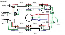
Here is the dual GLB that should, but did not work.
I was using CL-60 ( instead of resistors ) and diode bridges. The toroid is at the central to the amp. The secondaries are twisted.
The speaker outs are on the same side as the rca's. This layout is as-built ( minus the soft start, slow charge and speaker protection. )
I was using CL-60 ( instead of resistors ) and diode bridges. The toroid is at the central to the amp. The secondaries are twisted.
The speaker outs are on the same side as the rca's. This layout is as-built ( minus the soft start, slow charge and speaker protection. )
Attachments
Last edited:
Should the GLB be using resistors?
Also, the safety earth is connected near the IEC, but the GLBs are connected to chassis on other side of chassis. Would connecting them directly to chassis at safety earth make a difference?
Also, the safety earth is connected near the IEC, but the GLBs are connected to chassis on other side of chassis. Would connecting them directly to chassis at safety earth make a difference?
The CL60s are rated at 10 ohms at 25C, it might not make a difference but I like to see 5 ohms or so, maybe 2 CL60 in parallel, but I don't really think that is the problem. You might try running from the center tap of the transformer as your star ground point to each cap bank, not through a GLB each and have one GLB from the star ground to the chassis ground point. With two GLBs and slight difference in resistance of the thermistors might be enough to have a voltage difference that could be the source of the noise. Just something to try.
Good luck, ground loops are a pain in the *$$.
Good luck, ground loops are a pain in the *$$.
- Home
- Amplifiers
- Pass Labs
- F5 Turbo Builders Thread