Quieter with star grounded safety earth/GLB to center taps/capacitor banks.....
Still a bit of noise there when RCAs attached. Dead quiet when no RCAs involved. Will try resistors instead of NTC's tomorrow.
Thanks to all. Just printed out Joffe.
Still a bit of noise there when RCAs attached. Dead quiet when no RCAs involved. Will try resistors instead of NTC's tomorrow.
Thanks to all. Just printed out Joffe.
The CL60s are rated at 10 ohms at 25C, it might not make a difference but I like to see 5 ohms or so, maybe 2 CL60 in parallel, but I don't really think that is the problem. You might try running from the center tap of the transformer as your star ground point to each cap bank, not through a GLB each and have one GLB from the star ground to the chassis ground point. With two GLBs and slight difference in resistance of the thermistors might be enough to have a voltage difference that could be the source of the noise. Just something to try.
Good luck, ground loops are a pain in the *$$.
What you suggested was the original configuration. That noise started my hunt. At that time, I did not star ground the cap bank/CT.
Now, only two secondaries are paralleled each channel. One secondary is unused. There is a GLB using NTC between CT/cap common and safety earth. Safety earth now connects DIRECTLY to GLB's on chassis. No 100 nF capacitor is in place, just diodes and bridge.
I must say, I am enjoying the sound, but would like it to be *dead* quiet.
http://sound.westhost.com/earthing.htm
Has a good description of why the safety earth must be star grounded to the zero voltage line.
So yes, you must use the safety earth/chassis lug as the ground point for the power supply.
Has a good description of why the safety earth must be star grounded to the zero voltage line.
So yes, you must use the safety earth/chassis lug as the ground point for the power supply.
It sounds good, I'd like it a bit quieter if possible. It is a 4 pair/channel amp that has been initially biased at 0.222 V, or 50 watts RMS into 8 ohms. It should reach 75 watts RMS into 8 ohms ( 0.27 V bias) when biasing is complete.
OK, so here is what I am planning (Following Joffe, R2 is on F5 turbo Front end board):
1: Lift GND side R2.
2: Disconnect RCA shield from FE board
3: Connect RCA shield to GND side R2.
4: Connect GND side R2 to G via 4.75 ohm resistor
If this works, should it be made part of the FE board? ie, for mono block, change resistor to jumper. In stereo chassis, use 4.75 ohm resistor.
Is the 4.75 ohm resistor the right value or should it be 10?
THANKS
Last edited:
post3698 has no mention of the CONNECTION between the TWO interconnects into the Left and Right RCA input sockets.
Further there is no mention of the Main Audio Ground on either amplifier channel.
The drawing is incomplete.
Now read Joffe and you will SEE why the missing links are critical to understanding where the interference is getting in.
Further there is no mention of the Main Audio Ground on either amplifier channel.
The drawing is incomplete.
Now read Joffe and you will SEE why the missing links are critical to understanding where the interference is getting in.
I don't see where ESP says the Chassis to Protective Earth wire connection should be part of the star grounding of the zero Voltage line.Earthing (Grounding) Your Hi-Fi - Tricks and Techniques
Has a good description of why the safety earth must be star grounded to the zero voltage line.
So yes, you must use the safety earth/chassis lug as the ground point for the power supply.
.... Dead quiet when no RCAs involved. ...
This sounds to me like it is either a source issue or an issue with the input signal grounds. (As Andrew inquired about a few posts above) Does connecting the input grounds together externally with no source cause the same hum?
I don't see where ESP says the Chassis to Protective Earth wire connection should be part of the star grounding of the zero Voltage line.
ESP article said:It's not uncommon to see the mains safety earth connected near the mains inlet, and the signal earth connected somewhere else on the chassis. In isolation, this will never cause a problem. Once the equipment is connected to something else that's also earthed, an instant earth loop is created.
AndrewT,
I am clearly misunderstanding the Main Audio Ground (MAG) concept. I thought the drawing in 3698 shows that the CT as MAG?
Here is a drawing of how it is actually configured at the moment. The drawing shows that the paralleled secondaries are now split into two parts.
I am clearly misunderstanding the Main Audio Ground (MAG) concept. I thought the drawing in 3698 shows that the CT as MAG?
Here is a drawing of how it is actually configured at the moment. The drawing shows that the paralleled secondaries are now split into two parts.
Attachments
This sounds to me like it is either a source issue or an issue with the input signal grounds. (As Andrew inquired about a few posts above) Does connecting the input grounds together externally with no source cause the same hum?
No hum at all with external connection. Therefore, the Joffe solution of Figure 4 and 5 in his article simply does not apply.
I think I found the issue. When I reconnected LCHAN, there was still no hum. When I reconnected RCHAN, there was a bit of hum but now, only from the RCHAN!
Examining more closely revealed that I had left the CT of the unused 5th secondary attached to the CTs of the other secondaries in RCHAN.
It is MUCH improved now.
I will endeavour to measure the remaining hum with the DCB1 in circuit using a QA400. But today, I have other commitments.
THANK YOU.
I didn't understand your nomenclature of the first diagram in post3698.
Now the diagram in post3710 is less understandable
Now the diagram in post3710 is less understandable
Sorry for the confusion, and thanks for helping.
I will try to explain...
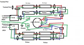
Starting at the toroid in the centre, the green lines coming out of the toroid represent the center taps. They are connected to two barrier strips, each of which is represented by the three small squares red/green/blue squares.
The green lines to Lcap and Rcap ( left/right channel cap banks) are the power supply commons for each channel's cap bank. They are connected to the barrier strip, as is the Ground loop breaker (GLB).
The GLB is a CL-60 and a 35 A diode bridge. The +/- sides of the bridge are connected to the ground point on the barrier strip. The AC sides of the bridge are connected to the single safety earth connection at the chassis. This is connected directly to the IEC safety earth tab.
The blue lines at Rcap and Lcap are the positive rails, the red are negative. The symbol "rect" indicates the rectifier, one per channel.
LFE and RFE are the front end boards. The Gshield is an RCA shield, the black + represents the signal input.
Does this make more sense?
Not shown is the Auxiliary transformer. It is an open frame transformer with dual secondaries, both 12 VAC. Total VA is 20. It was necessary to increase the VA due to the number of relays being operated. The regulated aux supply would drop out when a 12 VAC, 12 VA transformer was used.
The symptoms now, are that the amp is quietest when there no RCAs are plugged in. To hear noise, you must press your ear up against the speaker.
When either RCA is plugged in, then that channel starts humming. You can hear this from in the room, a few feet away, but very low volume.
When both are plugged in, both hum gently, but there is no increase in the volume of either. The Rchan RCA can be plugged into the Lchan and the same noise is heard... slightly different than the Lchan noise, which is more a pure hum.
AND, this happens with the DCB1 either OFF or ON.
Linking the left and right RCA shield with a jumper cable makes no added noise that I can detect.
Attaching a DAC with a two prong plug is silent.
This points to a ground loop between the DCB1 and the F5T. I will check the DCB1 to ensure that the safety earth and GLB are connected at a single point. The GLB in the DCB1 is a bridge with a 10 ohm resistor, connected to the chassis at a single point.
Is the NTC in the GLB a problem?
I'm clutching at straws here....
I will try to explain...
Starting at the toroid in the centre, the green lines coming out of the toroid represent the center taps. They are connected to two barrier strips, each of which is represented by the three small squares red/green/blue squares.
The green lines to Lcap and Rcap ( left/right channel cap banks) are the power supply commons for each channel's cap bank. They are connected to the barrier strip, as is the Ground loop breaker (GLB).
The GLB is a CL-60 and a 35 A diode bridge. The +/- sides of the bridge are connected to the ground point on the barrier strip. The AC sides of the bridge are connected to the single safety earth connection at the chassis. This is connected directly to the IEC safety earth tab.
The blue lines at Rcap and Lcap are the positive rails, the red are negative. The symbol "rect" indicates the rectifier, one per channel.
LFE and RFE are the front end boards. The Gshield is an RCA shield, the black + represents the signal input.
Does this make more sense?
Not shown is the Auxiliary transformer. It is an open frame transformer with dual secondaries, both 12 VAC. Total VA is 20. It was necessary to increase the VA due to the number of relays being operated. The regulated aux supply would drop out when a 12 VAC, 12 VA transformer was used.
The symptoms now, are that the amp is quietest when there no RCAs are plugged in. To hear noise, you must press your ear up against the speaker.
When either RCA is plugged in, then that channel starts humming. You can hear this from in the room, a few feet away, but very low volume.
When both are plugged in, both hum gently, but there is no increase in the volume of either. The Rchan RCA can be plugged into the Lchan and the same noise is heard... slightly different than the Lchan noise, which is more a pure hum.
AND, this happens with the DCB1 either OFF or ON.
Linking the left and right RCA shield with a jumper cable makes no added noise that I can detect.
Attaching a DAC with a two prong plug is silent.
This points to a ground loop between the DCB1 and the F5T. I will check the DCB1 to ensure that the safety earth and GLB are connected at a single point. The GLB in the DCB1 is a bridge with a 10 ohm resistor, connected to the chassis at a single point.
Is the NTC in the GLB a problem?
I'm clutching at straws here....
Hi BigE,
The NTC in the GLB is not likely the problem. It looks like a resistor to voltage and current. I had a Ground loop hum in a pair of monoblocks that could be solved by a wire tied between the chassis. Eventually changing each amps grounding point to one star ground for signal and a diode/resistor (CL60/bridge works the same)from star ground to a single chassis ground with the IEC mans ground solved the problem.
Another problem with hum turned out not to be the equipment but in the Mains Entry panel. After rewiring the Neutral side lines to one bus bar and the grounds to another and a hearvy gauge bond wire between the two and a 6 foot metal rod driven into the ground next to the panel and tried to the bond wire did all the equipment get quieter.
Just keep looking and trying.
Good luck,
John
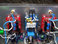
Thanks John. I think I have a clue of what is going on. I think perhaps doing what's in the photo is wrong -- the RCA input should be shielded.
What I noticed was that the blue heatshrink wrapped wiring on the Rchan was closer to the RCA than the Lchan. The caracteristic sound of the noise was different between the two channels. Bending that wire to the same distance away, changed the noise so that it was the same between the two channels.
I think that there is a ground loop created, but he resistors and NTCs reduce the noise a great deal, but without a shield, it can be induced in the circuit.
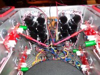
The Left and right sides of this back panel,from top to bottom, consist of RCA, FE board, Speaker protector, Speaker posts.
The center of the back panel, from top to bottom is Power switch, Soft start and IEC.
What I noticed was that the blue heatshrink wrapped wiring on the Rchan was closer to the RCA than the Lchan. The caracteristic sound of the noise was different between the two channels. Bending that wire to the same distance away, changed the noise so that it was the same between the two channels.
I think that there is a ground loop created, but he resistors and NTCs reduce the noise a great deal, but without a shield, it can be induced in the circuit.
The Left and right sides of this back panel,from top to bottom, consist of RCA, FE board, Speaker protector, Speaker posts.
The center of the back panel, from top to bottom is Power switch, Soft start and IEC.
Attachments

Discovery... both channels behave in exactly the same way. This is good. One was dropping out because the speaker cable was loose.
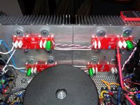
I changed the input wiring to a shielded cable, a quad star with one pair plus shield to RCA ground and one pair to RCA signal pin just to test. Was actually noisier than the twisted pair.
I changed the input wiring to a shielded cable, a quad star with one pair plus shield to RCA ground and one pair to RCA signal pin just to test. Was actually noisier than the twisted pair.
Attachments

Joffe figure three, identifying "parasitic capacitance from the mains to the low voltage windings" seems to be the most likely candidate.
In my case, I am trying to use a toroid that has 5 secondaries. Either using 5 in parallel feeding two rectifiers or 2 per rectifier and abandoning the 5th secondary will have a rather large parasitic capacitance, simply due to the nature of the windings.
Unfortunately, he does not say how to fix this. According to Joffe, it comes from capacitance that
Would that suggest that the transformer I am using in the F5T is bogus? If so, putting a large resistance in series with the rca ground would make matters worse, according to Joffe's test.
So, after adding a 10 ohm resistor in series with the Rchan shield connection, the noise in Rchan increased substantially. Lchan was unaffected -- ie still noisy, this indicates an issue with the transformer.
I am reluctant to accept this as the transformer is a BIG name. However, it does have 5 secondaries in parallel. Does this mean that we should avoid using multi-secondary transformers in parallel?
Thanks
In my case, I am trying to use a toroid that has 5 secondaries. Either using 5 in parallel feeding two rectifiers or 2 per rectifier and abandoning the 5th secondary will have a rather large parasitic capacitance, simply due to the nature of the windings.
Unfortunately, he does not say how to fix this. According to Joffe, it comes from capacitance that
Joffe said:can force currents through the grounds of the connections between devices. That current creates a voltage in the ground of the cables, a voltage that appears in series with, thus adding to the signals. Since currents come from the 60 Hz mains, we hear them ( and their harmonics) as a hum.
Would that suggest that the transformer I am using in the F5T is bogus? If so, putting a large resistance in series with the rca ground would make matters worse, according to Joffe's test.
So, after adding a 10 ohm resistor in series with the Rchan shield connection, the noise in Rchan increased substantially. Lchan was unaffected -- ie still noisy, this indicates an issue with the transformer.
I am reluctant to accept this as the transformer is a BIG name. However, it does have 5 secondaries in parallel. Does this mean that we should avoid using multi-secondary transformers in parallel?
Thanks
Last edited:
5 secondary transformer in a stereo amplifier is asking to be used as two pairs of windings dedicated to each channel without any need for paralleling.
This gives isolation between the channels just as a dual mono does but has to use a pair of dual secondary transformers.
A 4 secondary behaves, isolation wise, exactly the same as two dual secondary.
The 5th secondary just lies open circuit and unused.
This gives isolation between the channels just as a dual mono does but has to use a pair of dual secondary transformers.
A 4 secondary behaves, isolation wise, exactly the same as two dual secondary.
The 5th secondary just lies open circuit and unused.
- Home
- Amplifiers
- Pass Labs
- F5 Turbo Builders Thread