Why don't you just check the Jfets to avoid further stress.
Try this simple procedure from NP.
"I connect the Source and Gate to ground (for N) and measure the current.
With an 11 volt supply and assuming a typical value of 10 mA, use 100 ohms
in series with the Drain (the voltage drop across it will give you the Idss) for
a Vds of about 10V, and connect the other side of the resistor to +11V.
Reverse the supply polarity for P channel."
I just measured the Jfets I bought from Spencer using the above procedure. Instead of the 11V mentioned I used a 9V battery. Worked great.
Nash
Use a car, or motorcycle battery. 12V is close enough.
Or the standby battery in you fire/security alarm.
Or the standby battery in you fire/security alarm.
What happened with the 10K resistor in place of the FETS?
Wasn't able to do that yet... that and some jfet testing later tonight.
I don't think any of the Jfets are blown.
Tested the jfets with 9V battery and 100R resistor.
n-channel had +ve on drain and -ve on gate and source
p-channel had -ve on drain and +ve on gate and source
Original Jfet
K170 Idss=8.04mA
J74 Idss=8.04mA
The ones I put in fresh
K170 Idss = 8.00mA
J74 Idss = 8.13mA
So I put in 10K resistors across the drain and source on the FE board where Q1 and Q2 are supposed to be.
Q1
Drain - Gate =12.41V
Drain - source = 12.46V
Gate - source = 10mV
Drain - ground = 12.46V
Gate - ground = 0
Source - ground = 10mV
Q2
Drain - Gate =12.26V
Drain - source = 12.37V
Gate - source = 10.6mV
Drain - ground = 12.33V
Gate - ground = 0
Source - ground = 10.7mV
Now what?
Well I just measured at the BJT and I get 0.57V across the Base and Emitter so I think I'm good there.
Audiosan or anyone built a F5TV3 with roughly 40Vac secondaries with the first edition of the toecutter board?
Do you guys get these readings when if you disconnect the secondary boards?
Audiosan or anyone built a F5TV3 with roughly 40Vac secondaries with the first edition of the toecutter board?
Do you guys get these readings when if you disconnect the secondary boards?
Last edited:
I am befuddled. I would replace bjt's and go through test again. New bjt's, test the voltage from emitter to ground. If it is around 15V, reinsert Jfets and dsee what happens. Be super careful with orientation.
ok new bjt's in. These are the ones off the other channel that was never powered.
Nope, still 12.46 drain to gate on the 4793 side and 12.37V on the 1837 side.
Nope, still 12.46 drain to gate on the 4793 side and 12.37V on the 1837 side.
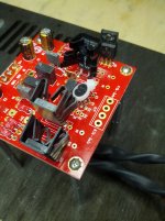
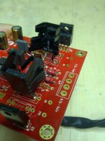
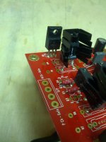
Attachments
Last edited:
......
Nope, still 12.46 drain to gate on the 4793 side and 12.37V on the 1837 side.
irrelevant (and logical) difference
proceed as Buzz said
Ok removed resistors, and put in the original jfets I had and left the new BJT's in.
I get the same results
Q1
tested on Q3 holes
drain - gate = 0.59V
drain - source = 0.58V
gate - source = 50mV
drain - ground = 0.62V
Q2
tested on Q4 holes
drain - gate = 0.51V
drain - source = 0.50V
gate - source = 50mV
drain - ground = 0.58V
I checked the caps they look like they are in the right polarity.
perhaps I should just leave this and add the secondary power board in?
Solder bridge on jfets?
I hope not... I must have soldered and desoldered these things like 10 times now....
I didn't see any...
It seems to me that there is a problem with the cascode. A drop of 4v with just a 10k load is highly unusual, and frankly the fact that it drops to zero when a forward biased jfet is connected, is expected.
I know you've replaced the BJTs, but I would go over that part of the circuit with a toothcomb. With a 10k resistor you should see pretty much the exact same voltage as open circuit. I have not seen the board layout unfortunately, so will be limited in helping out. I suspect either an elementary, symmetrical error or a busted component.
While testing, remember to short the input out completely - junction of jfet gates to be routed to ground. This will stop the jfets conducting and make troubleshooting marginally easier. You cannot set bias in this condition, for that you have to short the input pads of the board.
- Home
- Amplifiers
- Pass Labs
- F5 Turbo Builders Thread