I blew a JFet on one of my channels because I put them in the wrong place...
If you have a new pair from Spencer just replace the blown ones with the new pair.
L to R channel Jfet Idss doesn't need to be matched, the bias pots take care of that. What does matter is a good match between the N and P channel Jfet, on that channel's board.
Your good, my bad. It is in correct position. The drain of the sk170 should be to the positive rail.
oh ok... great, so I have everything hooked up correctly... why don't I see 15 V at the drain?
I'll have to check that.... just desoldered the jfets and bjts 🙂 I thought I had it wrong 🙂
Checked schematic as well so it does look correct.
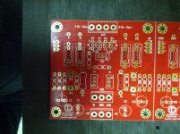
Note I used 12K instead of 10K at R25and 26 on account of the higher rail V.
Checked schematic as well so it does look correct.
Note I used 12K instead of 10K at R25and 26 on account of the higher rail V.
Easy way to figure what each resistor should drop is to divide rail voltage by total resistance. This wil give you your total current through that leg. Take that amount and multiply it times the resistors and you wil haev the Vdrop you shuld see. Your configuration should yield slightly less than 15V, i believe.
OK just checked.
I'm getting 16V almost exactly across both 4.75k resistors.
But 41V across the two 12K resistors (changed from 10k)
but my drain to ground is still less than 1V. (0.8 and 0.6 ) at the Jfets.
I'm getting 16V almost exactly across both 4.75k resistors.
But 41V across the two 12K resistors (changed from 10k)
but my drain to ground is still less than 1V. (0.8 and 0.6 ) at the Jfets.
I am not going to say that it is 100% that your Jfets are dead, but it seems like all you are getting is the Vbe drop of the bjt's. Perhaps others will confirm. IN theory, a biased Jfet shoudl provide resistance of some kind. This is how the voltage is formed at the drain. It appears yours are a dead short.
I am not going to say that it is 100% that your Jfets are dead, but it seems like all you are getting is the Vbe drop of the bjt's. Perhaps others will confirm. IN theory, a biased Jfet shoudl provide resistance of some kind. This is how the voltage is formed at the drain. It appears yours are a dead short.
hmm I wonder how that happened. other than the first turn on and the voltages I kept seeing it was never powered before?
How would I test to see if the jfets are dead? I never saw any magic smoke 🙂
Last edited:
Can't say with certainty, therefore I want. Perhaps the more learned can help and point out an error in my thinking. I have not heard of a 58V version. In theory it should not matter with the bjt's. Can't say for sure.
I'm lost without link to ref. schematic , considering all iterations (of everything) floating around

I'm lost without link to ref. schematic , considering all iterations (of everything) floating around
well it should be NP's F5TV3 schematic. However, the board was purchased on DIYaudio's site its V2.0. (toecutter board) hopefully there wasn't any major changes between that one and the one currently selling now.
No major changes.
Board size changed to match UMS, extra ground points added and more varied options for power resistors (spacing).
Board size changed to match UMS, extra ground points added and more varied options for power resistors (spacing).
Ok so perhaps I should remove the jfets and see if they are open. I only have a multimeter I guess I can only test for open and closed gate/drain/source....
alright desoldered the jfets, gate to drain and gate to source on both are not connected (open)
drain to source has resistance in the 3-4 K range.
Does this mean the jfets are ok?
drain to source has resistance in the 3-4 K range.
Does this mean the jfets are ok?
I'm back , after some time
pull all semis out , and test them
for Jfets - search for JFets matching - all you need is 9V battery and DMM
for mosfets - something more , but you'll manage
though , even if that seems complicated and over the top for one "simple repair" , you'll learn something and use these procedures later
pull all semis out , and test them
for Jfets - search for JFets matching - all you need is 9V battery and DMM
for mosfets - something more , but you'll manage
though , even if that seems complicated and over the top for one "simple repair" , you'll learn something and use these procedures later
- Home
- Amplifiers
- Pass Labs
- F5 Turbo Builders Thread