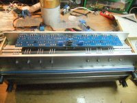
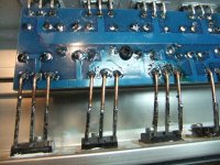
I have previously visited this thread, "F5 turbo is posted", for advice regarding the use of the cooling tunnel to F5 turbo V3. Now the construction of F5T V3 is well under way, and I find it appropriate to move over my questions, experiences and pictures to this thread
In order to utilize the PCB to the cooling tunnel as good possible, I have chosen to use the PCB from Jim's Audio.
All output N-FETs are matched, as well as all P-FETs . JFETs are matched so they have quite similar Idss (and > 8 )
Both channels are tested. On one channel biasmeasurement was similar within a few mV. In the second channel , however there is a difference of approx 35 mV
The question whether this is of any importance have been raised in this thread earlier. The ansewers from serveral members have been quite clear (# 2493.2481 and 2484 ): What I measures are not important, and therefore this will not take away a good nights sleep.
P3 affects offset measurements of the output. However, I chosse to set P3 in the middle position, since I have no ability to do THD spectra measurement/analysis (#2502)
Nashbap wrote
I am building a V3 Turbo with 4prs output devices. 34V transformer secondaries with estimated 45V loaded rails. I think I have enough heatsink to be able to bias at 0.31V across the paralleled 1ohm resistors to give bias current of 0.62A per device to give about 100W rms Class A into 8 ohms.
Looking at the Vishay MUR3020W chart for If vs. Vf it appears that at a Tj of 50C (Mosfet and diode side by side on heatsink at 50C) the diode starts conducting at about 0.42V which across 0.5ohm resistance equates to 0.84A. Does this not mean that in this example the diodes will not conduct until the amp leaves Class A?
This is exact what I am bulding.- I do have one 2x33V AC 660 VA transformer, and will recap another one to be equal.
Using MUR 3020 is for me something "new" in building NP. The last F5 I built did not have this diodes. To be on the safe side and not get in to a runaway the bias should not be higher than 0.31V across the paralleled 1 ohm resistors(like nashbap). I hope to regulate the blow to keep the temprature well under 50 C.
Does this sound reasonable??
I must admit I have not fully understood the benefits of MUR 302. Can anyone explain?
Eivind Stillingen
Attachments
when you crank the volume , current going from amp to speaker goes up
it's passed through source resistors ....... resulting in greater voltage loss across them , when current goes up
diodes are there to conduct when Urs is at/above diode voltage drop/treshold , keeping voltage losses at bay
it's passed through source resistors ....... resulting in greater voltage loss across them , when current goes up
diodes are there to conduct when Urs is at/above diode voltage drop/treshold , keeping voltage losses at bay
Looks like I need to cascode. My transformers that are supposed to be 24v are more like 27v. The two transformers are ~0.7v different at the secondaries. Is that an issue? I am a little disappointed in the tolerance.
Is that secondary voltage you measured no load? What is the line voltage where you live?
hello
was just finished building my F5Turbo v2 when i decided to go for a choke input supply
luckily I built mono amps, because after hooking up the finished supply, I did the usual reset of the bias pots to least resistance, so that I´d make a gradual startup
what I missed is that without any current draw, the choke input psu delivered 65v per rail and I blew out the back of the sk170 😱 and burned the rest of the transistors as well..
anyway it´s not a lot of money, but just to avoid a similar incident, I thought about readjusting the amp with the regular supply, substitute the reg supply with the choke input supply and restart connected to a Variac, and while adjusting the Variac readjust the bias and take it easy till I reach the wanted bias level.
Q: after having done this, will the amp on normal startup go immideately to full current draw, thus representing full load on the psu, so I don´t feed the amp to high voltage again? or is the current draw building up gradually?
best
Leif
if you arrange setup with Variac (going gradually , as you wrote ) , you're safe
later , amp will take care of itself - just bang the switch ......
later , amp will take care of itself - just bang the switch ......
ok thxs
so once adjusted it will not exceed rated psu voltage (approx 32vdc/rail) on normal startup?
best
Leif
so once adjusted it will not exceed rated psu voltage (approx 32vdc/rail) on normal startup?
best
Leif
nope
though ..... remember that choke input supply isn't happy solution if you intend to push it substantially outside of A class
though ..... remember that choke input supply isn't happy solution if you intend to push it substantially outside of A class
what bias level are you considering out of classA ?
why is this not a happy solution?
think I ran it @350mv with std supply
best
Leif
why is this not a happy solution?
think I ran it @350mv with std supply
best
Leif
I think that Pa covered that in several articles
from top of my head , I think that for regular T v2 principle is the same - A class up to twice Iq
so , when you go out of current envelope , there is Klunk !

from top of my head , I think that for regular T v2 principle is the same - A class up to twice Iq
so , when you go out of current envelope , there is Klunk !
Klunk is what happens when amps leave class A and enter AB. Nelson has an article, "Leaving Class A" which addresses the topic.
Just bias to 0.35 - 0.40V across the source resistors. Limit yourself when the following happens - a) heatsink temp is 55C and transistor pin 2 is 65C, and/or b) your total bias in watts is 1/2 the VA of your power transformer.
Klunk sounds fine - I've never heard it in any of these amps. 🙂 🙂 🙂
"Leaving Class-A" article here -- http://www.enjoythemusic.com/magazine/manufacture/0808/
Klunk sounds fine - I've never heard it in any of these amps. 🙂 🙂 🙂
"Leaving Class-A" article here -- http://www.enjoythemusic.com/magazine/manufacture/0808/
With lots and lots of heatsink and transformer, you need to be more careful, I suggest you read this from the original F5Turbo article --
We see that these devices will slowly start conducting at voltages just above the idle voltage across the 0.5 ohm Source resistors. It will be necessary to heat sink these diodes, remembering that their case is electrically connected.
The point at which the diodes conduct is temperature dependent, so you will want to set the bias so that it makes a nice transition above the bias point and doesn't run away when the amplifier gets hot.
If you are competent, fearless and also own a fire extinguisher, you can find this point. Just run the amplifier into a reasonably low impedance until it gets good and hot – as hot as you plan to let it get - ever. Then adjust the bias to a point below where the idle current starts to really take off. You should find that this point is around 0.4 volts across the 1 ohm resistors. If you are a fraidy-cat, then just set it at 0.3 volts, and conservatively fuse the AC line.
yes read that
that´s why I settled on the compromise of 0,35
worst that can happen is a few $ 😱
thxs
best
Leif
that´s why I settled on the compromise of 0,35
worst that can happen is a few $ 😱
thxs
best
Leif

- Home
- Amplifiers
- Pass Labs
- F5 Turbo Builders Thread