When in doubt....read Papa's words again:
about the diodes....from the article:
"....
We see that these devices will slowly start conducting at voltages just above
the idle voltage across the 0.5 ohm Source resistors. It will be necessary to
heat sink these diodes, remembering that their case is electrically connected.
The point at which the diodes conduct is temperature dependent, so you will
want to set the bias so that it makes a nice transition above the bias point and doesn't run away when the amplifier gets hot.
"
conclusion is ..
😀😀
put them in bucket full with motor oil ?

..to do it for first time ...i think ! ..." Baaaaad ZM ! "

All great explanations!!!!!
I think I got it figured out now,These diodes mur3020wt short out the source resistors as the temperature rises on the heatsink but only to a point,somewhere around .03 R and also allow a amount of thermal stability in resistance,as opposed to no source resistance which would allow thermal runaway,so it regulates the source current by temperature,a smart move by PAPA,lol.
So around 45 C is a good temp for this to occur.......Comments are welcomed!
Sometimes it takes a day or 2 for stuff to sink in,lol.
NS
I think Nelson was saying that the diodes are not a cure for, but instead a victim of thermal runaway like the mosfets are. I think the problem he was trying to address by using the MUR3020 diodes is that a ballast resistor of 0.5 R is needed for stability, but at high current draw there is excess voltage drop just when you need it the most. If you push 4 amps through a mosfet, there would be 2 volts lost from the rail voltage. The pair of diodes could limit the voltage drop to about 0.6 or 0.7 v. However, you do not want them to conduct at idle current (bias current) or you nullify some stability from the 0.5R resistor. Setting the bias current below when they conduct is necessary, but it you let them get hot, they can conduct much lower as their curve shows. Nelson recommended allowing some safety margin and putting some heatsinks on them. You do not want their temp to rise much and conduct at a lower voltage. This also requires a relatively low bias setting. He recommended 0.3 to 0.4 volts (0.6 to 0.8 amps) bias per mosfet, but try to measure it to make sure. One solution is lower the resistance to something like 0.33R but Nelson must have a good reason to recommend 0.5R and I tend to go with experience. In another post I suggested possibly using 4 diodes per mosfet in series/parallel to double the conducting voltage and allowable bias. Please understand that these diodes help the amp power while in AB mode. Concerning heatsinks, I think Buzzforb was right on in recommending the diodes have their own small heatsinks separate from the power mosfets. That way they probably would run much cooler, keeping the conducting voltage high and stable. I think that is what Nelson meant, but he would have to say for sure.All great explanations!!!!!
I think I got it figured out now,These diodes mur3020wt short out the source resistors as the temperature rises on the heatsink but only to a point,somewhere around .03 R and also allow a amount of thermal stability in resistance,as opposed to no source resistance which would allow thermal runaway,so it regulates the source current by temperature,a smart move by PAPA,lol.
So around 45 C is a good temp for this to occur.......Comments are welcomed!
Sometimes it takes a day or 2 for stuff to sink in,lol.
NS
What is the general opinion on matching the FET's for the F5 Turbo ? I read it in the F5 thread that for the normal version it is not so critical, but how does it affect in the case of two FET's / rail ( V1 ) ? Thinking about building one at 32V, 0.8A bias for my 87dB speakers.
Regards, Stefan
Regards, Stefan
What is the general opinion on matching the FET's for the F5 Turbo ? I read it in the F5 thread that for the normal version it is not so critical, but how does it affect in the case of two FET's / rail ( V1 ) ? Thinking about building one at 32V, 0.8A bias for my 87dB speakers.
Regards, Stefan
Yes, with more than one FET per rail, matching is important so the FETs dissipate like current.
I think you have a good explanation,,,
hi,
I will run some of those values and see how it does ,and if Papa says it works I would stick close to his values also,Thanks for your Time !
 I will search your other post and read them also!
NS
hi,
I will run some of those values and see how it does ,and if Papa says it works I would stick close to his values also,Thanks for your Time !
I will search your other post and read them also!NS
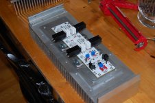
Little Progress with TeaBag's boards
Love the diode heatsinks...perfect for my solution.
Size of your main heatsink is ?
Looking forward to your findings driving that board really hard.🙂
I dont know how much i can push them. Two 12" XXLS woofers wired in parallel, playing at uncomfortable levels wasnt pushing them. I'll give it my best attempt. I have considered adding the other 2 pairs of devices, making Rs 1 ohm, and cutting biad through each fet to 400mA. IT seems like the wrong direction, but i just read how the XA160.5 has each fet biased at only 7watts. I was quite shocked at this and perhaps read it wrong, but it has me considering the benefits/consequences of more pairs at lower bias, vs less pairs at higher bias.
Easy , More Prs with lower Bias.... 🙂 A friend has the XA30.5, i cant get over how cool it runs, nothing like an F5 ..
It was definitely interesting to read how low the XA.5 amps were biased. I know they are SUSY and haev other mechanisms at work that I do not fully understand, but interesting none the less. I have the amp together and fighting whether to strip it and paint it. I know if i finish it and begin to listen, I will take forever to actually paint and finish.
well , not exactly low biased , if you read what's written in datasheet for each one
30.5 - 113W/ch
160.5 - 250W/ch
dissssssssipation , of course
30.5 - 113W/ch
160.5 - 250W/ch
dissssssssipation , of course
Thanks for more complete info, but still a low per fet bias. Question? Does the transconductance of multiple pairs add causing a reduction in noise and distortion? Also, I think I remember Nelson saying that multiple pairs alos had a beneficial effect on Capacitance and drive/bandwidth issues.
- Home
- Amplifiers
- Pass Labs
- F5 Turbo Builders Thread