.
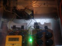
This is my Messy Stripboard wiring, I could have used the Diyaudio power supply boards.
as you see Im using a whole bunch of strips as the ground points.
Its a bit messy but hopefully will be ok!
View attachment 351011
I don't have a problem with your PSU wiring on veroboard, but then I am not as experienced as the others here.
When I am doing similar stuf I like to double the power traces with "rigid", I mean single core power supply cable like 3x1,5mm2 (AWG 16 ?).
I just strip the insulation off, bend it as needed, tack it down to the veroboard and solder to the caps.
Easy, cheap and good for 16 Amps on european 240V networks.
Your local hardware store should have some cut-offs for 3 x nothing.
Hey, anybody over there have any experience using the SumR Primrose transformers? Is it worthwhile to have 4 secondaries compared to 2? Antek is currently out of stock of the 600VA 24V transformers. I wonder why? 🙄

Last edited:
Last edited:
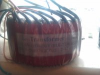
Btw the transformer Im going to use has Primarys as
0v - 115v - 230v
BLK- YLW - RED
So I presume for my 230v I need to use Just Black and Red ? not all 3
so my question realy is does anything have to be done with the 115v wire ?

I cannot wire the powersupply as seen In Nelsons articles ? with thermistor. Any ideas
Sounds like a plan 🙂
0v - 115v - 230v
BLK- YLW - RED
So I presume for my 230v I need to use Just Black and Red ? not all 3
so my question realy is does anything have to be done with the 115v wire ?

I cannot wire the powersupply as seen In Nelsons articles ? with thermistor. Any ideas
I just strip the insulation off, bend it as needed, tack it down to the veroboard and solder to the caps.
Sounds like a plan 🙂
Last edited:
Yes.
The Yellow is just a center-tap to the primary winding. Just ignore the yellow center-tap and wire as any other transformer with 230V single primary.
The Yellow is just a center-tap to the primary winding. Just ignore the yellow center-tap and wire as any other transformer with 230V single primary.
Last edited:
Thanks, brilliant just leaves the issue what to do with that thermistor in schematic.
actualy It seems like i can just wire thermistor In series.
actualy It seems like i can just wire thermistor In series.
Stick it on live lead, downstream of fuse. All it does is limit current at startup to help keep fuses blowing when the caps charge.
Thanks, brilliant just leaves the issue what to do with that thermistor in schematic.
actualy It seems like i can just wire thermistor In series.
That's exactly what I did with mine.
Stick it on live lead, downstream of fuse. All it does is limit current at startup to help keep fuses blowing when the caps charge.
which is very usefull ! 😀 now's time to let the wiring up fun begin.
Last edited:
Some of the Pass PSU schematics show a CL60 for each 110/120Vac winding.
If you series connect these for 220/240Vac primary, then one should series connect a pair of CL60 for use at the higher voltage.
If you series connect these for 220/240Vac primary, then one should series connect a pair of CL60 for use at the higher voltage.
Cheers 🙂
Was thinking before, in the PSU... GND doesn't go direct to chassis but goes thru the rectifier etc first.
I have a B1 buffer in the same chassis. its GND goes directly to the Chassis, so If i connect that ground to the F5 which will probably end up happening, would that be a problem ?
I could isolate the B1 from chassis but would be a pain to do.
Last edited:
you must
"two" audio gnds must be one , isolated from chassis via NTC or diode bridge or whatever other proper way
"two" audio gnds must be one , isolated from chassis via NTC or diode bridge or whatever other proper way
Inside a conductive Chassis each channel that has it's own dedicated and isolated PSU must have ONE Main Audio Ground.
Any Channels that share a PSU must have ONE Main Audio Ground.
I don't think there are any other arrangements. Comments please.
Any Channels that share a PSU must have ONE Main Audio Ground.
I don't think there are any other arrangements. Comments please.
Hi Alazira,
I used 100 Ohm and 100nF/63V for the snubbers.
The 0.22 Ohm is appropriate for my 2SJ201/2SK1530 output devices, cause they handle 'only' 12A max. I saw it in the F5X thread.
An additional advantage is that with 1.25 A there is idle only around 0.3 V over the resistors and diodes, which is a value Papa named to be safe...
Walter,
could you kindly point me to the relevant posts in the F5X-thread concerning this issue - I am just trying to get my head around it (building with SJ/SK as well).
Thanks,
Max
sorry, it's not the F5X thread...😱
It's here: http://www.diyaudio.com/forums/pass-labs/206240-f5-turbo-posted-5.html#post2896992
Also in the F5X they are using 0R22 and in every other design I have seen, these MOSFETs are combined with 0R22 resistors... for example the updated Crescendo from Elektor.
Edit: if I remember correctly in the F5X thread schematics was also a 0R18 for one side of the amp.
Last edited:
sorry, it's not the F5X thread...😱
It's here: http://www.diyaudio.com/forums/pass-labs/206240-f5-turbo-posted-5.html#post2896992
Also in the F5X they are using 0R22 and in every other design I have seen, these MOSFETs are combined with 0R22 resistors... for example the updated Crescendo from Elektor.
Edit: if I remember correctly in the F5X thread schematics was also a 0R18 for one side of the amp.
Thanks for the link Walter, I did find some info in the F5X thread as well though....
Will dig further into it and ask questions here.
Max
Inside a conductive Chassis each channel that has it's own dedicated and isolated PSU must have ONE Main Audio Ground.
Any Channels that share a PSU must have ONE Main Audio Ground.
I don't think there are any other arrangements. Comments please.
That is how I did my KSA50 clone and it is dead quiet. Hear nothing with my ear to the speaker.
One audio ground per channel with it's own PSU, these are then connected via loop breaker circuit (bridge/CL60) to the chassis, which is connected to the safety earth.
In most cases, the value of Rs in a power output stage is chosen to provide enough voltage drop to ensure thermal stability under operating conditions. It is basically there to slow down that mosfet. THe SSR100 does not need a Rs over currents of 1-1.2A because it has a negative tempco, meaning that at higher bias, higher temps generally cause a reduction in bias vs an increase. MOst mosfets, like IRF 240/9240, Fqa's, and TOshibas, have a postive tempco. If you do not ballast them with a source resistor, you risk thermal runway in a situtation where ther are sudden increases in temp or current. IN most cases, these two things are happening simultaneously, as increases in current cause increases in internal temp and vice versa.
Folks:
Please forgive what may quickly turn out to be a regretable inquiry, but I'm building my F5T BOM and would appreciate parts recommendations on two components -- the anti-oscillation caps (C3 and C4 on NP's schematic) and the 75 degree thermostat. I'm not knowledgable enough (yet) to understand the importance of any differences I've seen in the data sheets.
Regards,
Scott
- Home
- Amplifiers
- Pass Labs
- F5 Turbo Builders Thread
