I enlarge my fet holes, as an M3 tap is impractical IMO.
is this possible 😕 got an old amp(cayin 270p) 🙂 with problems regarding bad treads. fets are under the board so clamping's not possible 😡
edit: could I take a 5mm drillbit and drill the hole bigger ??
Last edited:
Yes. I do it with every amp. A standard fet will not except a 6-32 screw as it is slightly bigger than M3. Luckily M3 holes can be easily enlarged using just the 6-32 screw. Just use vise grip pliers to hold fet and go to town on that bad boy. Often though, I kick it up to 8-32 so i can use larger, tougher tap.In this case, I will use a bit to enlarge the hole.
If worried, just practice on cheap, extra fets. i think you can take an M3 to M4 with out too much trouble. Just retap hole
If worried, just practice on cheap, extra fets. i think you can take an M3 to M4 with out too much trouble. Just retap hole
Last edited:
Hi All,
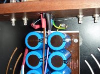
May I ask for a little advice? I thought I should build the power supply part of the F5 first then the audio. However I turned it on for the first time and it blew the small 1.25A fuse immediately, however the large bank of PSU caps still where giving out about 5v dv after 30 seconds. The fuse in the plug is still fine.
I have been over the wiring twice now and can't see any mistakes. I should say that I went for the more powerful transformer to enable me to get 50W output. What do you think I should try to fix my issue?
Attachments
Draw how you wired it. It will cause you to go back over it as well as give us something to go by.
Hi All,
May I ask for a little advice? I thought I should build the power supply part of the F5 first then the audio. However I turned it on for the first time and it blew the small 1.25A fuse immediately, however the large bank of PSU caps still where giving out about 5v dv after 30 seconds. The fuse in the plug is still fine.
I have been over the wiring twice now and can't see any mistakes. I should say that I went for the more powerful transformer to enable me to get 50W output. What do you think I should try to fix my issue?
It is not clear images, place a scheme.
If all is well, increase the fuse to 2A, and do not forget the link CLC-60 in primary toroidal.
Hi Guy's thanks for a quick response.
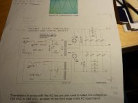
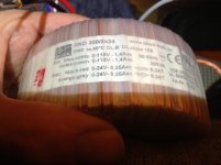
I have attached the schematic from firstwatt.com and a close up photo of my transformer
I have used the 240 V diagram as I live in the UK.
I have connected the blue and white together with the thermistor, this could be a mistake as they are shown as a pair on the transformer label, have I made a mistake? 😱
Is my second mistake that I wired up the earth from the mains power to the chassis when I should only have connected it to the CL60 thermistor?
I will also try a 2A fuse next time
Attachments
I had my v2 running on 1A slow blow for months. The reason I wanted you to draw and not post pics is that it might help you find an error. If you draw while checking, you might just draw you mistake. Maybe you spot it, maybe we do, but it gives us something to check.
Last edited:
Hi Guy's thanks for a quick response.
I have attached the schematic from firstwatt.com and a close up photo of my transformer
I have used the 240 V diagram as I live in the UK.
I have connected the blue and white together with the thermistor, this could be a mistake as they are shown as a pair on the transformer label, have I made a mistake? 😱
Is my second mistake that I wired up the earth from the mains power to the chassis when I should only have connected it to the CL60 thermistor?
I will also try a 2A fuse next time
It is a mistake. For 220V, connect white and violet of the transformer to the thermistor and the other two to the power line through switch and fuse.
not sure but this schematic is for a standard F5.
The F5T is fed 32v after capacitor bank and should use a "beeefier supply".
If I recall, there was a rectifier bridge tied to ground.
See the schematic of the f5T power supply.
The F5T is fed 32v after capacitor bank and should use a "beeefier supply".
If I recall, there was a rectifier bridge tied to ground.
See the schematic of the f5T power supply.
Hi Guy's thanks for a quick response.
I have attached the schematic from firstwatt.com and a close up photo of my transformer
I have used the 240 V diagram as I live in the UK.
I have connected the blue and white together with the thermistor, this could be a mistake as they are shown as a pair on the transformer label, have I made a mistake? 😱
Is my second mistake that I wired up the earth from the mains power to the chassis when I should only have connected it to the CL60 thermistor?
I will also try a 2A fuse next time
You have a toroidal 2X24V, is build an F5 Turbo V1 with a 300VA toroidal?
necplusultra - The F5T PSU as drawn by Nelson uses a single bridge, with the 'center tap' formed between the two windings as ground. That's how you use a single bridge in a bipolar supply.
There is nothing stopping one from using (in a F5Turbo) the dual bridge supply configuration as shown in the original F5 PSU. It can't hurt, and double bridges have some advantages.
You are completely correct in saying that there should be more capacitance in a Turbo (a 'beefier supply') than a original. The Stereo Turbo v2 uses some 80,000uf per rail.
Finally took closer look and read. Alniva is correct, you have your primary windings wrong. If you fixed that, all should be ok, hopefully.
Steve I would recommend making yourself a light bulb tester which puts the live through the bulb and so won't power up fully if you've made a mistake.Saved my a-- on a couple of occasions.
Hi Guys
Thanks all for your recommendations! I have now changed the wiring configuration of the transformer as you suggested Anilva.
When I switch the power on the transformer hums as I would expect, however instead of getting the 32 v DC I'm after I have 70volts showing on my digital multimeter. Is this so high because there is no load?
Regards
Hi Buzzforb
I connected my meter to the plus terminal of C8 and the minus to the minus of C6. (Ref the standard F5, PSU schematic I posted yesterday)
Thanks again
steve
I connected my meter to the plus terminal of C8 and the minus to the minus of C6. (Ref the standard F5, PSU schematic I posted yesterday)
Thanks again
steve
You got exactly what you should. Connect black probe to centerpoint/ground(bottom of c8), and the other probe to either of the previous spots.
Hi buzzforb,
I tested as you suggested, wow it works +35 v either side.
I appreciate your advice, have a nice day.
😀
I will now start to build the audio boards.
Regards
Steve
I tested as you suggested, wow it works +35 v either side.
I appreciate your advice, have a nice day.
😀
I will now start to build the audio boards.
Regards
Steve
SteveHolt -
With the black probe (common) attached to GND, and measuring with the red probe of your DMM, you should have positive 35VDC on the V+ and negative 35VDC on the V-
With the black probe (common) attached to GND, and measuring with the red probe of your DMM, you should have positive 35VDC on the V+ and negative 35VDC on the V-
Last edited:
- Home
- Amplifiers
- Pass Labs
- F5 Turbo Builders Thread