Apples and Oranges. -40 C and F are =. Stick to one scale 25C is about 77F. 55C is about 131F.
F5 bias problems.
Hello everyone, I don't know if this is the place to ask for help.
I built an f5 - v3 diyaudio board and have a problem adjusting the bias on one of the channels.
The right channel is stable 0.60 v at R7 / R8, the left channel oscillates between 0.57 v and 0.65 v approximately at R7 / R8, rises slowly and then slowly decreases, the offset is 0.
I don't know if this is normal and I don't know how to solve it, so I ask for help.
The amplifier works but I'm afraid of an accident. I don't understand anything electronic, I follow the assembly instructions and make the measurements, but I don't know anymore, so I ask for help to those who know.
Thanks.
Subdias.
To change my f5 enclosure i removed f5 pcb and re install into new one. Then i made a mistake wrong polarity connection V+ power source to V- and V- power source to V+. Even i correct it after, now i saw smoke on ground cable connection on pcb and R2 resistor heat like hell. Pcb version v3.0. Any guess about which componenets get damaged?
desolder and check with matching jig each one of JFets and mosfets
that , if simple diode test didn't show a short
that , if simple diode test didn't show a short
The right channel is stable 0.60 v at R7 / R8, the left channel oscillates between 0.57 v and 0.65 v approximately at R7 / R8, rises slowly and then slowly decreases, the offset is 0.
Given the slow nature of this, it is likely the thermistor circuit.
I don't think it will do any damage in the meantime.....
Thank a lot, Mr. Nelson.
Should I replace the 2 thermistor (th1/2)and the 2 resistor (R21/22)?
Should I replace the 2 thermistor (th1/2)and the 2 resistor (R21/22)?
I would look to see if I could find significant DC voltage difference across the part
in the bias circuit as compare with the other channel.
in the bias circuit as compare with the other channel.
Dear experts.
What resistance type and tolerance do you recommend for the 1w and 3w ones?
Just de get the best of this circuit!
Thanks a lot Nelson, my daughters and me are really enjoying your amazing design!
What resistance type and tolerance do you recommend for the 1w and 3w ones?
Just de get the best of this circuit!
Thanks a lot Nelson, my daughters and me are really enjoying your amazing design!
Your regular parts. 10% tolerance is fine - you are going to be adjusting the
current through it with the pots anyway, and the tolerance on bias is larger than that.
If you want to be fussy, use non-inductive, but even that isn't a big deal.
current through it with the pots anyway, and the tolerance on bias is larger than that.
If you want to be fussy, use non-inductive, but even that isn't a big deal.
Dear experts.
What resistance type and tolerance do you recommend for the 1w and 3w ones?
Just de get the best of this circuit!
Thanks a lot Nelson, my daughters and me are really enjoying your amazing design!
For 3W, either Panasonic metal oxide, or Vishay CPF.
For 0.5W Vishay CMF 55, or maybe Caddock radial.
I have completed the assembly of my F5 boards and I plan to build my own chassis and I am trying to determine what size heat sink to use. I plan to use heat sinks from HeatsinkUSA but I'm not sure what dimensions to use. How does one go about figuring this out?
Thanks
Thanks
Also you could make some rough calculation and look after a heatsink with C/W number that is small enough for your requirements. E.g. if you tolerate 60 C on heatsink with ambient 25 C then you have 35 C temp raise to "play with". If you put let us say 80W pr. side out in heat then you should look for a 35/80 = 0.4 C/W heatsink. Then to be safe maybe look for 0.2 - 0.3 C/W heatsink (assuming 80W dissipation pr side.....have not checked).
I built mine with the deep 3U chassis, I can hold my hand on it even after a few hours of pushing it
I built mine with the deep 3U chassis, I can hold my hand on it even after a few hours of pushing it
Flamethrower1, did the 3U come with any holes drilled or did you need to drill and tap?
6L6, thanks ! I'm guessing that longer cooling fins would be better, correct? They offer them 1" up to nearly 3" and some with serrated fins.Centurion - a good rule of thumb is approx 4x6” (10x15cm) of heatsink per output device.
Thanks
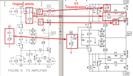
Hi folks, I am sure a lot of you will be able to answer my question: if I compare the original design of F5 with the v3 schematic, i see a few changes (obviously) - are these changes something essential that will change the sound of the amp, or are just because of the turbo compatibility? I don't understand these schematics, so it's not obvious for me. Thanx for the clarifications!
Attachments
- Home
- Amplifiers
- Pass Labs
- F5 power amplifier