Ah.
Assuming you have -
0.6v (or close) measured across R6 R7 (meaning the bias is full on both sides of the circuit)
and close to zero DC offset at the speaker terminals
a difference in bias of 20mV (0.02v) across 0.47ohm is approximately 43mA and absolutely nothing to worry about. 😀
If it were my amplifier I'd say that's very close to perfect, pour a glass of wine and enjoy the music as I dream about the next project to build.
I have built F5 with significantly more difference between the two sides than what you have and it worked and sounded beautifully.
I have 0.47v one side & 0.50 on the other at R8 or R7, I took the 2 measurements on each side left/right.
The offset at the speaker terminals fluctuate -0.0002 ~ +0.0002.
So you confirm it is good, lovely, I am very happy.
The offset at the speaker terminals fluctuate -0.0002 ~ +0.0002.
So you confirm it is good, lovely, I am very happy.
as long you have one side good for Iq and practically 0 offset at output , who cares for other side Iq value , except to confirm that you didn't put wrong resistors in source 🙂
Zen....realise I have no idea if this could have an effect or not, so you confirm it hasn't, thanks to take your time to tell, I appreciate.
Yes Jim, the thing is running permanently, now I may consider speakers DIY, I am better at that !
I am thinking of a Klipsch Jubelee "of the poor", a two ways for sure of this nature.
I am thinking of a Klipsch Jubelee "of the poor", a two ways for sure of this nature.
At the moment my F5 and BA3 Pre resting in storage. I never get intended level of gain for my Ditton 332 speakers. No idea why. Maybe speakers are hard to drive or power hungry?
Noticed one thing; I first used 50k (log) pot for ba3 then replaced it with 10k stepped attenuator log pot. I was getting more or less ok volume with 50k pot, but with 10k I have to turn volume more than before.
So my question is: what may be the best value for pot between ba3 and f5?
Noticed one thing; I first used 50k (log) pot for ba3 then replaced it with 10k stepped attenuator log pot. I was getting more or less ok volume with 50k pot, but with 10k I have to turn volume more than before.
So my question is: what may be the best value for pot between ba3 and f5?
The potentiometer value is a function of your source to the BA3 pre. What are your sources?
Does you setup play loud (too loud...?) if the volume knob is turned all the way up?
Does you setup play loud (too loud...?) if the volume knob is turned all the way up?
The potentiometer value is a function of your source to the BA3 pre. What are your sources?
Does you setup play loud (too loud...?) if the volume knob is turned all the way up?
You're right. I forgot this.. Pot is between source and ba3 🙂
My sources are different. Have turntable and bugle pre,cassette deck and DIY PCM61 nos dac. And cd player...
I have to turn pot to mid point to have reliable sound level with 10k. Never tried full.
My question is; I was turning 50k pot lower than this 10k to have the same sound level. Why is that?
The 50k pot is easier to drive by your sources, but that’s a simplistic answer -
You are expecting the volume to be very very very loud at a certain knob rotation, probably 11 O’Clock or thereabouts, because thats what we were all acclimated to from 70-80’s stereos.
If the system plays too loud with the knob all the way up, you DO have enough gain and you just need to twist the knob further for a given volume, and enjoy the finer control you have over playback levels. 🙂 🙂 🙂
The 50k pot is easier to drive by your sources, but that’s a simplistic answer -
twist the knob further for a given volume, and enjoy the finer control you have over playback levels. 🙂 🙂 🙂

Your amp is fine, as Zen Mod wrote. However, if the system consisting of the GND wires, the preamp and the F5 form a loop that picks up noise, you might be able to improve the noise with hum breaking resistors.
@mbrennwa
School me on where I'd put the HBRs on the F5. Noob style. I've seen the Bonsai diagram, it's unclear to me if I'm soldering 15ohm resistors someplace on the board or what seems to be an inline splice just after the ground wire leaves the board?
The RCA input jacks must be at earth potential to avoid potential shock hazard. Same for binding posts if they have exposed metal parts.
But these are insulated from the chassis.
Law requires that you must connect the circuit ground to mains ground which in turn connects to chassis ground.
However this may generate hum because multiple pieces of equipment are connected to earth as well, and the currents that flow along this may face less resistance than your interconnects. Therefore though your signal itself comes through the interconnect, the return uses the earth path (it automatically chooses the lowest resistance).
The HBR 'breaks' this 'loop' and creates more resistance in the earth path for the signal. Thus the signal is 'forced' to go through the interconnects. In practice this can connect anywhere (as long as there is no other parallel path) between chassis ground and circuit ground.
If you have a single power supply for both channel, the supply midpoint is a good place to get the connection from. The 'resistor' needs to have excellent high frequency performance and very high current capability. Hence it is customary to use a capacitor in parallel with it, and a pair of back-to-back diodes (usually formed out of a bridge rectifier, this will limit the voltage to 0.7V and protect the resistor from excessive dissipation). This 'leg' of the 'resistor' connects to your power supply ground.
The other end of this resistor is connected to mains earth, which hopefully has a short, fat connection to the chassis using a bolt and washer.
If you have dual mono supplies, you need two of these.
This looks more the description of the ground lift, also done with a CL 60. In the Bonsai paper there’s a slide showing both hbr and ground lift (page 56) where you can see how to install them. From memory a modification to the board is needed... I may however be wrong here.
Indeed he was the one from which I read about it first.
there may actually be a way to insert the hbr without board modification if speaker return is connected to star ground point and hbr is inserted between board ground and star point. However speaker wires will not be tightly twisted anymore
there may actually be a way to insert the hbr without board modification if speaker return is connected to star ground point and hbr is inserted between board ground and star point. However speaker wires will not be tightly twisted anymore
The 50k pot is easier to drive by your sources, but that’s a simplistic answer -
You are expecting the volume to be very very very loud at a certain knob rotation, probably 11 O’Clock or thereabouts, because thats what we were all acclimated to from 70-80’s stereos.
If the system plays too loud with the knob all the way up, you DO have enough gain and you just need to twist the knob further for a given volume, and enjoy the finer control you have over playback levels. 🙂 🙂 🙂
Isn't this an elegant reply ? Sure it is !
More capacitance and LEDs
Hi,
I've built my F5 3 years ago and love it! But I have 2 questions 😉
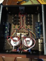
But I want to make 1 big change and that is add more capacitance to the amp. Currently there are 2 Amplimo 225VA toroidal transformers that feed 2x60.000uF Mundorf caps. But from reading some other posts, that might not be enough capacitance, and I hear a very slight hum (50hz) when my ear is buried in my speaker.
So I got 12 new 22.000uF caps in total, 2x132.000uf for my F5, which might be a bit too much, but, hey why not...
1. Am I correct that 60.000uF is not enough capacitance for a 225VA transformer, and therefore I might hear some hum?
2. Or, as I have also a Pass Pearl 2 phono amp, are the LED's on the cvilier v3 boards not meant to be on long leads and function as pretty lights on the front panel? (so the LED's should be as close as possible on the boards)
thx!
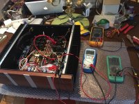
And also I added 2 images, 1 a bit old, of the internals of the amp, 1 of the new F+T 22.000uF caps on new boards
Hi,
I've built my F5 3 years ago and love it! But I have 2 questions 😉
But I want to make 1 big change and that is add more capacitance to the amp. Currently there are 2 Amplimo 225VA toroidal transformers that feed 2x60.000uF Mundorf caps. But from reading some other posts, that might not be enough capacitance, and I hear a very slight hum (50hz) when my ear is buried in my speaker.
So I got 12 new 22.000uF caps in total, 2x132.000uf for my F5, which might be a bit too much, but, hey why not...
1. Am I correct that 60.000uF is not enough capacitance for a 225VA transformer, and therefore I might hear some hum?
2. Or, as I have also a Pass Pearl 2 phono amp, are the LED's on the cvilier v3 boards not meant to be on long leads and function as pretty lights on the front panel? (so the LED's should be as close as possible on the boards)
thx!
And also I added 2 images, 1 a bit old, of the internals of the amp, 1 of the new F+T 22.000uF caps on new boards
Attachments

What is 20C above ambient for the heatsink?
This has been bugging me and is probably something simple that I'm not grasping.
If ambient room temp is 22C, then 20C above that is 42C, or 107.6F.
But, if ambient is 72F, then adding 20C (68F) is 140F.
My F5 runs somewhere in between those at 120-122F. Which one is correct?
This has been bugging me and is probably something simple that I'm not grasping.
If ambient room temp is 22C, then 20C above that is 42C, or 107.6F.
But, if ambient is 72F, then adding 20C (68F) is 140F.
My F5 runs somewhere in between those at 120-122F. Which one is correct?
- Home
- Amplifiers
- Pass Labs
- F5 power amplifier