Just a quick question for Mr. Nelson Pass
The XA200.8 is pure Class A.
John Atkinson recently performed some measurements, power measurements into 8, 4 and 2 Ohms.
Clipping measurements @ 1% THD (1kHz).
• Pass Laboratories XA200.8 monoblock power amplifier Measurements | Stereophile.com
Are those maximum figures from Class AB?
When does it start to switch, or does it?
From this review, two days ago:
• Pass Laboratories XA200.8 monoblock power amplifier | Stereophile.com
Thank you for any further light you can beam.
Cheers,
Bob
Last edited:
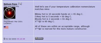
The suspicion was apparently based on a 47.8 deg c. sink temperature,
putting it between Blimey and Crikey. (see chart below)
The output is rated at 200 watts into 8 ohms, and the amplifier is rated
Class A to this figure.
By actual measurement, the amp draws 700 watts out of the wall, and
leaves Class A at 430 watts peak, which is 215 watts rms and 7.33 amp
peak.
Our criteria for "leaves Class A" is that the"other half" of the push-pull
output circuit is less than 5% of the idle bias current.
A 7.4 Amp peak current is consistent with the 4 amp bias on each side,
and also consistent with total sink dissipation of 560 watts, which
with an 80% line power factor makes it also consistent with the AC draw.
Attachments
Klunk!
47.8C sink temperature at 70W dissipation each.
Very nice heatsinks !
Thank you Mr. Nelson Pass.
☆ How you and Zen Mod did get an encircled star below your joining date?
Does it require earnings?
☆ How you and Zen Mod did get an encircled star below your joining date?
Does it require earnings?
I like the 'klunk' when it leaves class A. Can you make it more second order harmonic?`
(yes, this is a joke).
(yes, this is a joke).
☆ How you and Zen Mod did get an encircled star below your joining date?
I'll find out after I figure out how my phone works......
Thank you Mr. Nelson Pass.
☆ How you and Zen Mod did get an encircled star below your joining date?
Does it require earnings?
Those who support DIYAUDIO by an annual donation. 🙂
http://www.diyaudio.com/index.php?pageid=donations
Hi everyone
I hope I am not polluting here, I am a huge fan of Don Keele’s CBT 24 and the association with a FW J2 is sublime but the amp is definitely underpowered for these low efficiency arrays.
I have in mind the build a CBT 24 with a re-wiring allowing four F5 modules to power a série of 6 drivers per board.
The 4 modules for each channel should fit in a 5U 500 chassis, maybe biased a little lower than usual, and with a beefy PSU.
Some of you may know already, but in this particular array, the upper drivers have their level lowered gradually by 3 and then 6dB.
I would do this atténuation on the related board instead of using resistances es in the speakers.
Could someone just tell me how to lower the F5 gain by 3 or 6dB ?
Thanks a lot in advance !
Pierre-Antoine
Could someone just tell me how to lower the F5 gain by 3 or 6dB ?
Use an input attenuator, a series resistor and a shunt resistor.
Changing the values for R9 and R10 would be the simplest way.
You'd need to decide what input impedance you want for the amp first.
For example, if you want an input impedance of 50k,
then R9=R10=25k, for 6 dB less gain.
Please don't alter the feedback network instead.
Last edited:
You can RAISE the gain by changing the feedback resistor values...check the f5 turbo article. That will get get you the gain difference you desire.
You could also lower the gain by playing with the feedback network but it’s likely the amp will become unstable.
Changing the feedback network changes the character of the amp though...they will sound different, it does not just effect gain. I would think some sort of attenuation before the power amp would be a better option for level matching. Even a simple l pad resistor setup (f5 has a high input impedance, easy to do this) would probably a better and more flexible option.
Well...obviously yes, but to me there is something elegant, and unusual, in using multiple small FW amps to power clusters of Fullrange drivers, filterless, instead of using a bigger amp.
But that’s just me😉
But that’s just me😉
I would rather listen to one F5 heavy biased at say 2A than 4 F5 biased at 500ma though.
Is anyone running an F5 at 2A? I thought 1.7A was pushing it!
- Home
- Amplifiers
- Pass Labs
- F5 power amplifier