Finished my F5 yesterday, tested it with my SJ92X Horn Speakers, and in direct comparison to my old amp (Marantz) the F5 seems to have a lack of bass in sound.
Moreover the trebles sound "metallic". Does anybody had such an effect before?
I suppose a technical problem, buy my equipment for measuring ist very poor.
Bias is set to 1,2A, temp of the amp after 2h about 60°C. No Hum or other probs.
For the test I first connected the CDP directly to the F5, second test with the preout of the Marantz amp, same effect.....
Even changed the polarity of one speaker, does not solve the problem.
Any further ideas? 🙁
Input: 2SK170 and 2SJ74
Output: IRFP9240 and IRFP240
The 2SJ74 I bought from china, via ebay: TOSHIBA 2SJ74 TO-92 P CHANNEL JUNCTION TYPE (LOW NOISE | eBay
Maybe these are not genuine...
Building the amp I had some problems with biasing ( post http://www.diyaudio.com/forums/pass-labs/121228-f5-power-amplifier-1462.html#post4200881 ) , can this be a reason for my sound probs?
At the end, the paralel resitor was set to 8k2.
Last edited:
the j74 you have bought via Ebay from China are almost certainly fakes.
You should have tested them before fitting to prove they are a high gm device and fit within the Idss range for their grade.
You should have tested them before fitting to prove they are a high gm device and fit within the Idss range for their grade.
Even though the J74's from China might be fakes, and a bit noisier than bona fide devices, if you purchase 25 pieces you are going to find some with gm of 8mS or more. Paralleling 2 devices will get you in the ballpark.
The gain of the amplifier is lower with the low gm devices, you should be able to set the correct bias with P1/P2, but may have to change the value of R5/R6. Doing so will change the gain of the first stage. You may increase the gain of the amplifier back to the design value of ~15.3dB by increasing the value of the feedback resistors, R9,10,11,12
The gain of the amplifier is lower with the low gm devices, you should be able to set the correct bias with P1/P2, but may have to change the value of R5/R6. Doing so will change the gain of the first stage. You may increase the gain of the amplifier back to the design value of ~15.3dB by increasing the value of the feedback resistors, R9,10,11,12
Hi everyone,
For my F5 PS capacitor bank I'm using four 33,000uf caps for a total of 132,000uf.
I have some spare caps.
Will I get any benefits if I'll add two more caps in the bank?
Thanks
IK
For my F5 PS capacitor bank I'm using four 33,000uf caps for a total of 132,000uf.
I have some spare caps.
Will I get any benefits if I'll add two more caps in the bank?
Thanks
IK
132mF seems to be 33mF||33mF on each supply rail.
You could try 33mF R 33mF||33mF on each supply rail.
The amp still sees the low impedance of the parallel pair
The mains hum is attenuated slightly more, due to the rCRCC PSU, instead of rCC
I don't think you will hear, nor measure, any improvement by going to rCCC
You could try 33mF R 33mF||33mF on each supply rail.
The amp still sees the low impedance of the parallel pair
The mains hum is attenuated slightly more, due to the rCRCC PSU, instead of rCC
I don't think you will hear, nor measure, any improvement by going to rCCC
On the F5, like a lot of classA power amps, it's the TYPE of power supply capacitor that makes the difference, not the size - ie: 2 X 10,000uF per rail is quite adequate if the caps used are good ones, particularly on the second cap in the filter.
Nearly all the 33,000uF caps are what's known as "slow" caps, so if you want a 'slow sound' in your amp, they'll do quite well as the F5 amp has a 'pretty quick' characteristic and it might just work out well - sorry for the jargon but it does describe the effect pretty well
Also, unless you are careful, using bypass electrolytic caps (or foils caps, for that matter) on the amps pcb isn't always a good thing and can easily produce problems
I think you are doing a disservice to capacitors..............Nearly all the 33,000uF caps are what's known as "slow" caps, so if you want a 'slow sound' in your amp, ............
It would be far better to use supply rail decoupling to ensure the fast transients have a source of energy to supply the current demands of the load.
very low esr capacitors can indeed introduce stability problems.using bypass electrolytic caps (or foils caps, for that matter) on the amps pcb isn't always a good thing and can easily produce problems
Select the correct capacitors to suit the duty.
Big standard duty electrolytics in the PSU, (not smps types).
Adequate decoupling at the main current consumers on the PCB using higher esr, ultra low inductance capacitors, (not plastic film types).
Last edited:
Yes, Andrew, no doubt you are correct - the only 'big caps' in this range that I have had much to do with have been Rifa, BHC (& Aerovox), Siemens, Mundorf, Kendeil, and such ones and the only 'quick ones' are the first 2 at 33mF in the F5 amp (IMO, I hasten to add).
After saying that, it also depends on what speakers they are to be matched-up with and what components used to build the F5 amp, etc, etc.
I gather from 'IK's post above that he has some 33mF ones and wanted to know if adding more would be of any benefit, so my suggestion of using 10,000uF ones is unhelpful indeed
If you have a total of 8 caps, IK, I would just setup the simple C-R-C for each rail and for each channel, as Andrew indicated above - you will have to work hard to get 'humm' in this amp if you follow normal setup methods - it's a pretty good amp in this regard too.
If those 33mF caps are Rifa's, and you've used some of those 'hyper fast diodes', you may want to try adding a series resistor before the first cap (the ripple cap) in a C-R-C filter to make it an R-C-R-C filter (the Rifa's are a bit tricky for this) - so it goes like diode -> 0.05R (or 0.1R) -> 33mF -> 0.1R (or 0.15R) -> 33mF for each rail and each channel .
I have had some trouble with the F5 with a variety of bypass caps on the amp's pcb itself, even with the power supply caps (the p/s output caps) quite close to the pcb - but it's not a major concern as it's pretty easy to remove, or change them - some people seem to get a lot of benefit from this bipass method, so it appears it's an "it depends' type of thing
It's good to see another F5 coming together
as I see it - there is just thickness difference to count in and ...... higher torque possible
in case that you go to clamping route , instead of simple bolting , I wouldn't hesitate
in case that you go to clamping route , instead of simple bolting , I wouldn't hesitate
Tanto Megio as one would say in Venice
(we reserve the right not to post any technical information while public library is open)
(we reserve the right not to post any technical information while public library is open)
higher torque possible
Relationship between torque and clamp pressure : T = C * D * F
T is torque in Nm
D is diameter screw/bolt in m
F is clamping force in N
C is coefficient/factor, 0.34 for unlubricated
Footprint area of a TO-247 case is 3-3.3 cm2.
Mounting torque is 10lb-in, aka ~1.13 Nm.
Mounting hole of a TO-247 is 3.4 mm (M3 fastener, or 5-40 US)
(outcome in N is the reason why it's very easy to snap a screw/bolt by overtorquing)
Last edited:
http://www.diyaudio.com/forums/attachments/pass-labs/228347d1308768302-my-f5-new-f5-2206-007.jpg
N/C graph is on specification sheet for kerafol
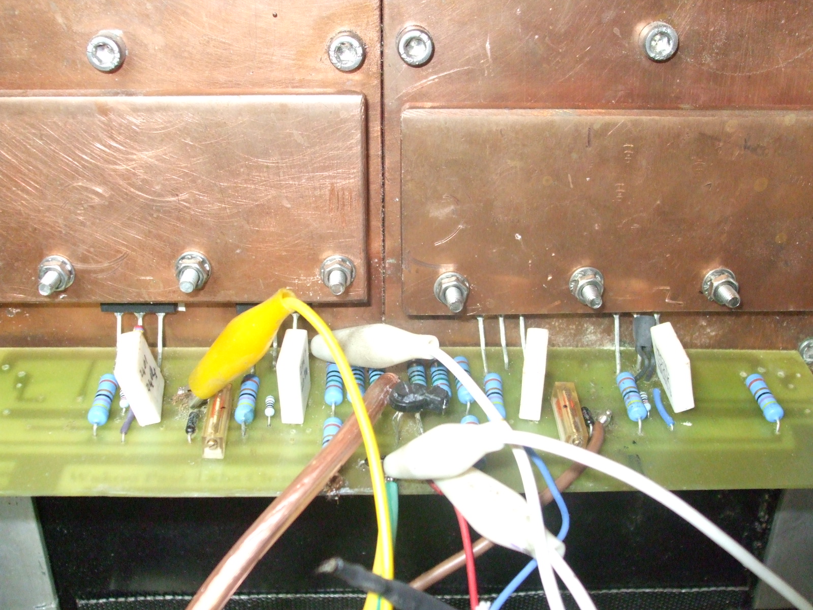
I am using M4 captive bolts (heads buried in copper plate).
Care is to be taken not to crack plastic mos-fet body
N/C graph is on specification sheet for kerafol
I am using M4 captive bolts (heads buried in copper plate).
Care is to be taken not to crack plastic mos-fet body
- Home
- Amplifiers
- Pass Labs
- F5 power amplifier