Hi All,
First post after much reading. I'm building an F-5 with/for my son. A few missteps along the way but we're learning. My strengths lie mainly in the design/fabrication side of things; while I have a basic understanding of electronics most of what goes on even in a "simple" amp like the F5 is still sorcery and magic to me.
I'm a big DIYer - in all aspects of life - both because I love to create things, and because it's the only way I can afford some of the nicer things in life.
To the latter end, I've located some transformers that I can get at a good price. They're not the ideal dual 18V secondaries solution, but I think that a pair of them might work well in the F5. Here's an excerpt from their description:
"At 110Vac, the output is 2-10Vac windings, each center tapped, at 8 amps or you can tie the 2-10V windings together and create 20V at 8 amps."
Do you think a pair of these would be a good fit for this amp?
Thanks for any advice you can lend. I look forward to sharing more of this project when we actually have something to show...
Two 20Vac transformers can be used to create a dual polarity supply.
The DC voltage will be a little bit higher than for a standard F5.
Check how hot your heatsink get as you gradually wind up the output bias current. Take it slowly, maybe may than an hour, to ensure the output stage is fully warmed up and yet not too hot.
The DC voltage will be a little bit higher than for a standard F5.
Check how hot your heatsink get as you gradually wind up the output bias current. Take it slowly, maybe may than an hour, to ensure the output stage is fully warmed up and yet not too hot.
Thank you Andrew. The boards are mostly populated. Waiting on delivery of the PSU boards. Scored 39" of 6" x 1 3/4" heat sink at the local metal scrap yard for the price of scrap aluminum ($4/lb.). Was originally planning on using the 10" HSUSA stuff but this was half the $ and I came up with a really sweet case design (IMHO) around the 6" stuff. From searching the forums it looks like 6" x 8" of heat sink per output device should be sufficient... am I correct? With the material I have, I could go 9" without mucking up the design, but I'd prefer to keep it at 8"
don't expect the real McCoy for bargain prices.
Maybe you should define Asia.
I bought a bunch of V-grade JFETs and a load of NOS R-core transformers from THL in Taiwan, for peanuts.
The transformers were even more interesting, due to THL willing to send them over on a cargo ship, as an exception. (think very heavy box by airplane)
Same deal with vendors in Singapore, Malaysia, Hong Kong, and Japan.
Chance of buying genuine JFETs now through the web, from a guy around the corner named McCounterfeit, is just as high/low.
Now I understand that my cd player is not fit to drive F5.
Waiting to build the preamplifier , I use the smartphone as the source.
I only have a small problem :
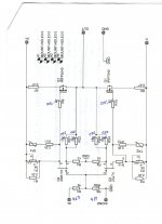
in a channel can not get over 0.52 Volt across R12 . I do not understand if the problem is in P2 or Q2 or Q4 . Once I read the answer to this problem , but I can not find it.
However, the sound is very good.
Waiting to build the preamplifier , I use the smartphone as the source.
I only have a small problem :
in a channel can not get over 0.52 Volt across R12 . I do not understand if the problem is in P2 or Q2 or Q4 . Once I read the answer to this problem , but I can not find it.
However, the sound is very good.
Add resistance to resistor in parallel with bias pots. (R3, R4 in original schematic)
You are pretty close, adding 1K or 2.2K in series with existing 2.2K will likely be enough.
You are pretty close, adding 1K or 2.2K in series with existing 2.2K will likely be enough.
Just change the F5 gain from 6times to 7times and most CD players will be able to drive the F5 into clipping.Now I understand that my cd player is not fit to drive F5.
Waiting to build the preamplifier , I use the smartphone as the source.
I only have a small problem :
in a channel can not get over 0.52 Volt across R12 . I do not understand if the problem is in P2 or Q2 or Q4 . Once I read the answer to this problem , but I can not find it.
However, the sound is very good.
I did Idss measurement, so 2SK170BL have 8-9 mA and 2SJ74GR is between 3-5 mA. Is It too much difference?
You can use P3, or tweak the value of the drain resistors to suit Idss.
I don't bother, P1 and P2 have sufficient adjustment range for 99% of situations if your drain resistors are high enough.
I don't bother, P1 and P2 have sufficient adjustment range for 99% of situations if your drain resistors are high enough.
How to change the gain ?Just change the F5 gain from 6times to 7times and most CD players will be able to drive the F5 into clipping.
R5 R6 R7 R8 are already 220 ohms !
I have to change R10 and R9 ?
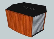
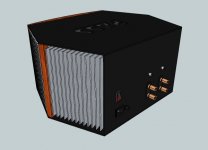
Here's my chassis design for my son's F5. Of course there's a big leap from design to successful execution, but this really won't be much more difficult than a rectangular box. Hope the use of the Pass logo in this manner is kosher.
Attachments
How do you plan to thermally couple the two sinks to each other? A bent heatspreader, or a PCB that angles the devices in that way?
Looks funky 😀
Looks funky 😀
Do the heat sinks need to be thermally coupled to each other? Each output MOSFET will have 48 sq. in. of heat sink. The MOSFETS will be mounted off-board with short leads, so no need to bend the boards 😉
220r is not an F5.How to change the gain ?
R5 R6 R7 R8 are already 220 ohms !
I have to change R10 and R9 ?
What have you built?
F5 has a 50r : 10r feedback ratio.
The 50r is usually a pair of paralleled 100r.
This gives a gain of 6times, +15.56dB
For an output of 27W into 8r0 an F5 will need 14.7Vac/6 = 2.45Vac
Not many sources have an output this high.
A little bit of added gain is useful if you want a CDP with a maximum output of 2Vac to 2.2Vac to be able to drive the F5 to just reach clipping.
As with all amplifiers one may want some added gain for low output voltage sources.
Changing the gain/feedback resistors to 220r||220r:10r increases the sensitivity to 1.23Vac to drive the amplifier to just reach clipping @ 27W into 8r0.
Most sources can give a maximum output around 1Vac and more.
There are some sources that give <500mVac and these generally need some added system gain for loud reproduction levels.
Thanks AndrewTF5 has a 50r : 10r feedback ratio.
The 50r is usually a pair of paralleled 100r.
This gives a gain of 6times, +15.56dB
For an output of 27W into 8r0 an F5 will need 14.7Vac/6 = 2.45Vac
Not many sources have an output this high.
A little bit of added gain is useful if you want a CDP with a maximum output of 2Vac to 2.2Vac to be able to drive the F5 to just reach clipping.
As with all amplifiers one may want some added gain for low output voltage sources.
Changing the gain/feedback resistors to 220r||220r:10r increases the sensitivity to 1.23Vac to drive the amplifier to just reach clipping @ 27W into 8r0.
Most sources can give a maximum output around 1Vac and more.
There are some sources that give <500mVac and these generally need some added system gain for loud reproduction levels.
What you said is valid for 4r0 speakers?
The gain is set by the feedback resistors.
The gain does not change.
The maximum ClassA power and the maximum ClassAB power is determined by the output current of the amplifier and the impedance of the load.
4r is half 8r.
Therefore ClassA power is halved into a 4r load.
ClassAB power is doubled into a 4ohm load.
an F5 is roughly
25W of ClassA power into 8ohms and 25W of ClassAB power into 8ohms.
But
12.5W of ClassA power into 4ohms and 50W of ClassAB power into 4ohms.
The power specifications read very differently in changing from 8ohms to 4ohms.
What have you built?
The gain does not change.
The maximum ClassA power and the maximum ClassAB power is determined by the output current of the amplifier and the impedance of the load.
4r is half 8r.
Therefore ClassA power is halved into a 4r load.
ClassAB power is doubled into a 4ohm load.
an F5 is roughly
25W of ClassA power into 8ohms and 25W of ClassAB power into 8ohms.
But
12.5W of ClassA power into 4ohms and 50W of ClassAB power into 4ohms.
The power specifications read very differently in changing from 8ohms to 4ohms.
from post14474220r is not an F5.
What have you built?
What have you built?
Last edited:
The gain is set by the feedback resistors.
The gain does not change.
The maximum ClassA power and the maximum ClassAB power is determined by the output current of the amplifier and the impedance of the load.
4r is half 8r.
Therefore ClassA power is halved into a 4r load.
ClassAB power is doubled into a 4ohm load.
an F5 is roughly
25W of ClassA power into 8ohms and 25W of ClassAB power into 8ohms.
But
12.5W of ClassA power into 4ohms and 50W of ClassAB power into 4ohms.
The power specifications read very differently in changing from 8ohms to 4ohms.from post14474
What have you built?
This is
Attachments
is 4,7k equal to 4700 or 47000?
Why did you change that?
To increase the RF filter of the capacitance inherent in the input jFETs?
Better to have added a fixed (non changing) capacitor across R6.
Keeping the source impedance lower usually gives the amplifier a chance for better performance.
Your gain and thus your feedback are changed.
The gain is now 220||220r / 10r +1 = 12times (+21.6dB). That reduces your feedback by about 6dB.
It also increases your sensitivity to 1.22Vac for full power (27W or 14.7Vpk).
Most sources are capable of driving your modified F5 into clipping.
Do you really need more gain?
Why did you change that?
To increase the RF filter of the capacitance inherent in the input jFETs?
Better to have added a fixed (non changing) capacitor across R6.
Keeping the source impedance lower usually gives the amplifier a chance for better performance.
Your gain and thus your feedback are changed.
The gain is now 220||220r / 10r +1 = 12times (+21.6dB). That reduces your feedback by about 6dB.
It also increases your sensitivity to 1.22Vac for full power (27W or 14.7Vpk).
Most sources are capable of driving your modified F5 into clipping.
Where did this come from?I understand that my cd player is not fit to drive F5.
Do you really need more gain?
Last edited:
oloppolo - I suggest you change the input resistor (R5 in your schema) to something near 1K. The 67K input shunt is fine. Everything else looks appropriate for a F5 with no limiter.
As Andrew says, with 220R feedback resistors your CD player should be able to drive the F5 to clipping.
As Andrew says, with 220R feedback resistors your CD player should be able to drive the F5 to clipping.
- Home
- Amplifiers
- Pass Labs
- F5 power amplifier