This is a god idea [I should do too]; it is because the input capacitances of tewo P-FETS and two N-FETS differ.
One extra trick: connect the 500 pF not to ground but to the source resistor of the P-FET. That way the static value is reduced just like the gate-source resistance dynamically on the N-side.
Are you suggesting a cap from the drain to source of the P-ch MOSFET?
The cap I was suggesting was from the drain to the gate of the P-ch MOSFET, balancing the greater Cgs of the N-ch MOSFET.
So it looks like I may have a bad cap in my F5, the problem is that it is a NOS cap I bought on here and I am unable to get more. Since I have to chance the PS I am figuring that I might as well switch from a CRC to a CLC. My problem is that I am unsure of the proper gauge of inductor I need. Is the recommended gauge of the wire in a F5 (16-14g) power supply the same as the recomended gauge of an inductor. This is what I am looking at picking up.
Sidewinder 2.25 mH Air Core Inductor 16 AWG: Madisound Speaker Store
If someone has a more economical solution, i would love to know about it. It seems to me that if I could get some cheap magnet wire, I could just coil it up and make my own but until I have a good meter that sounds like a lost cause.
certainly doubled output power , tripled current reserve , and quadrupled perception of aural excitement

all that tnx to better ripple filtering , comparing to CRC
all that tnx to better ripple filtering , comparing to CRC
Are you suggesting a cap from the drain to source of the P-ch MOSFET?
The cap I was suggesting was from the drain to the gate of the P-ch MOSFET, balancing the greater Cgs of the N-ch MOSFET.
You see it correct, I talked Cgs! I read your post wrong.
 You do feedback.
 For my idea:
See papa on the subject of balancing the capacitances..
The reason I like this 'balancing' is that it makes the top and bottom side behave correctly in phase at high frequencies (the way I look at it), because the input JFETS see different impedances if just left alone.
By carefully measuring the Gate current of each device at
8 volts rms into 8 ohms (1 amp rms) at 1 KHz, 10 KHz, and
100 KHz we can measure the total input capacitance. By
performing the same experiment without a load, we can separate
out the Cgd. Under these conditions the total input capacitance of the
IRFP240 is about 75 pF and the IRFP9240 is about 60 pF.
He is talking about the F4; the F5 is not a follower and differs of course because now they suffer from the Miller effect.
I found some other posts:
Jacco said on the input capacitance:
Ciss = Cgs + Cgd
Crss = Cgd
Cin = Cgs + Cgd - Av*Cgd = Cgs + (1-Av) * Cgd
Maybe your idea is better?
done deal
Makes me wonder what the Biggie-est ever made CM iron core choke (in a CLC) is ?

(that looks difficult, no way I said that)

Thanks Zen, unfortunately I don't know coil length or diameter. I did find that the DCR is .54. Close but no cigar. Will I be ok as long as the DCR is under .4, no matter what the gauge is?
I am right in thinking that 2.2mH is about right, right?
That is very helpful, thank you. That site says that the inductor can handle 400w. With my PS being ~ 25V after rectification, that looks like it would make my limit 16A. Should I really be concerned that the dcr is .52 instead of being under .4? It's close but I am unsure how that will affect the circuit.
Are these viable options?
http://www.parts-express.com/pe/pshowdetl.cfm?PartNumber=255-108
Digi-Key - M8383-ND (Manufacturer - 1140-222K-RC)
From what I understand about inductors, if they have a metal core they saturate and become useless. From my searching on diyaudio there is some confusion when using an inductor for a CLC filter.
Last edited:
WIRES.CO.UK 2.120mm to 2.800mm Polyester Enamelled Copper Wire
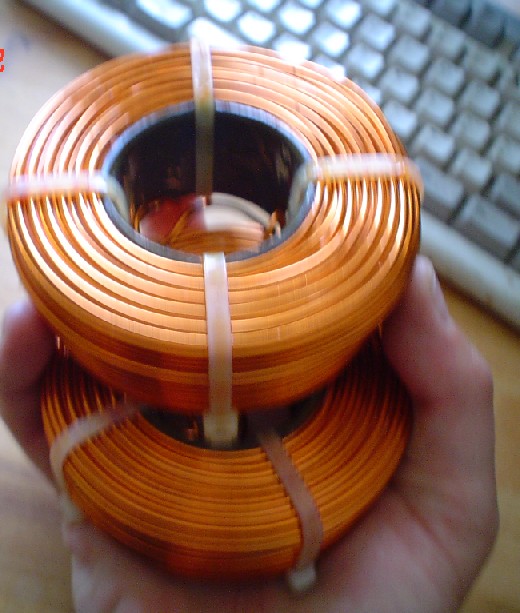
I got 2 kilos (is sold by weight) of this stuff and made up 2 coils.
IS about 12 AWG 2.24 mm
Realy thick stuff and a pain to wind up
Next time I will wind the 2 core side by side and make a comon Coke
Even beter that way
+ I went for CRCLC
As Zen said stay at less than 0.4 homs and you be ok
Here conversion table
wires.co.uk : Conversion data for AWG
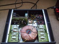
Coils on the botom right (not that one can miss them )
I got 2 kilos (is sold by weight) of this stuff and made up 2 coils.
IS about 12 AWG 2.24 mm
Realy thick stuff and a pain to wind up
Next time I will wind the 2 core side by side and make a comon Coke
Even beter that way
+ I went for CRCLC
As Zen said stay at less than 0.4 homs and you be ok
Here conversion table
wires.co.uk : Conversion data for AWG
Coils on the botom right (not that one can miss them )
Attachments
Example (though these are 2.5mH, 11 gauge, and over 4.5lb each, you don't want that)
http://www.diyaudio.com/forums/atta...3d1119351988-krell-ksa-50-pcb-krell-coils.jpg
http://www.diyaudio.com/forums/atta...3d1119351988-krell-ksa-50-pcb-krell-coils.jpg
Yeah that the way look like I got half the weigth I needed or to put this another way
only 1 mH.
Now what about winding them wires side by side and make a comon mode coke
Will it be worth the efforth to re wind up my 2 coils?
only 1 mH.
Now what about winding them wires side by side and make a comon mode coke
Will it be worth the efforth to re wind up my 2 coils?
You see it correct, I talked Cgs! I read your post wrong.
For my idea:
See papa on the subject of balancing the capacitances..
The reason I like this 'balancing' is that it makes the top and bottom side behave correctly in phase at high frequencies (the way I look at it), because the input JFETS see different impedances if just left alone.
He is talking about the F4; the F5 is not a follower and differs of course because now they suffer from the Miller effect.
I found some other posts:
Jacco said on the input capacitance:
Maybe your idea is better?
A way of testing the 2 approaches would be to look at the square wave response. If the frequency response of the 2 sides is balanced, the square wave over/under-shoot should be the same (other than phase) for the rising and falling edges. I haven't done this test because I haven't gotten around to building an adequate square wave generator. Even at 192KHz from my sound card, the square wave has relatively slow edges.
Choke loaded is a completely different topology. It only works within a certain limit of constant current, and it then regulates the output!
The choke is a current generator (sort of) and has to be of high quality, otherwise it will make awful noises - and it will radiate all around the place. So that is why they must be big and developed for this purpose. This is indeed not for sissies. [I made a tube amp with such an LC power supply, loading to 2.200 mF 400 volt - good regulated but noisy].
:LOL
- Home
- Amplifiers
- Pass Labs
- F5 power amplifier