naah.......
I'm Modesty (Blaise) ZM
at least Jaccolina is always here , to keep me firmly by the earth/soil

I'm Modesty (Blaise) ZM
at least Jaccolina is always here , to keep me firmly by the earth/soil
Officer, i didn't lay a hand on him, and if i did, it definitely was not firmly and in plain sight all the time.
Nice fat and juicy SMPS, i hope.
Nice fat and juicy SMPS, i hope.
did you answer so quickly just to become #12,000?
..........and we're only 79k away, from TWO MILLION views....! 🙂
(But who's counting?)
Has anyone compared a smps with a regular linear supply?
I'm tempted to try it!
Fran
SMPS could be quite good as you're in Class A which means that the base load on the SMPS is constant. This really simplifies things from an audio perspective.
When will Members stop spreading this false ClassA claim?
There are very few ClassA implementations that draw constant current from the supply rails. These few exceptions are even more rarely implemented.
The vast majority of ClassA implementations do not draw constant current from the supply rails.
For a good example of an exception see F5x.
There is also a Thread dealing with the special case of constant ClassA power current draw.
Probably I Missed it!
could any one tell me why the Thermistor and the 2.2K Resistor are different in the revised Scheme? They are not coming from the Rails but now from the Pot.
What is the advantage of this change?
Can Cviller's board be used (2011-2-9 version) to set it up as an F5 Turbo V1?
Nils
could any one tell me why the Thermistor and the 2.2K Resistor are different in the revised Scheme? They are not coming from the Rails but now from the Pot.
What is the advantage of this change?
Can Cviller's board be used (2011-2-9 version) to set it up as an F5 Turbo V1?
Nils
not coming from the Rails but now from the Pot.
not really...
the revised version inserts the 0R47 source resistor in the thermistor circuit.
V1: temperature compensation is static only.
V2:the voltage variation across Rsource makes the compensation dynamic also.
My 2 cents.
Last edited:
The way I see it is that a resistor to "earth" (the rail) is in parallel with the drain resistors and pot (parallel the values) so that means that the amplification changes with temperature. Even if we believe that the temperature stabilizes.
Now when we connect it to the source then the value cannot be paralleled as the virtual impedance of the resistor connected this way is HIGHER! This is because there is feedback from the dynamic changing Vs.
Very smart move!
Now when we connect it to the source then the value cannot be paralleled as the virtual impedance of the resistor connected this way is HIGHER! This is because there is feedback from the dynamic changing Vs.
Very smart move!
I think i got it.
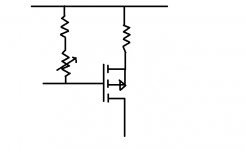
For compensation, you want to act on the Vgs of the mosfet.
In V1 compensation network takes into account the source resistor (Vgs + VRs) ans so, sees some kind of nfb. (See fig.)
In V2 compensation is directly source to gate. Which is more efficient.
For compensation, you want to act on the Vgs of the mosfet.
In V1 compensation network takes into account the source resistor (Vgs + VRs) ans so, sees some kind of nfb. (See fig.)
In V2 compensation is directly source to gate. Which is more efficient.
Attachments
I think i got it.
For compensation, you want to act on the Vgs of the mosfet.
In V1 compensation network takes into account the source resistor (Vgs + VRs) ans so, sees some kind of nfb. (See fig.)
In V2 compensation is directly source to gate. Which is more efficient.
I think the only difference is 0,5R (Source Resistor) and the voltage drop across it which does not matter that much. The V2 has the advantage that it is easier to find a layout with the ntc closely mounted to the mosfet.
Regards
Flo
the voltage drop across it which does not matter that much.
Depends how many amps are flowing.
Depends how many amps are flowing.
Of course. The second variant is more exact as stated above, I think the principle remains the same.
Last edited:
So what if one get realy good set of matched mosfets and drop the source resistor to 0.25 (or there about) homs.
what efect this will have? (soundwise)
I was thinking to use up the 100 or so Futabas 0.47 I have to make ideal sets for each Mosfet
what efect this will have? (soundwise)
I was thinking to use up the 100 or so Futabas 0.47 I have to make ideal sets for each Mosfet
I use 0R22 in one of my F5s without problem.
So is half (or there about) Vdrop and Half dissipation + diodes efect will ame in later for a V3
And sound wise or such ?
- Home
- Amplifiers
- Pass Labs
- F5 power amplifier