I used PBJ interconnects which is 3 twisted wires, 2 - earth, 1 + , (only type of shielding used when I was a kid and still works,)
But out of preamp all 3 connected, into F5 only "+ red" to "SIN " on F5 board and 1 " -- blue" wire to GND on F5 board, "unconnected Black" then is a twisted shield that goes all the way back to pre amp and connected at that point only.
But out of preamp all 3 connected, into F5 only "+ red" to "SIN " on F5 board and 1 " -- blue" wire to GND on F5 board, "unconnected Black" then is a twisted shield that goes all the way back to pre amp and connected at that point only.
I found a couple of 1k5 bulk foil resistors in my parts bin would it be ok to use them instead of the 1k0 resistors[R9] on the amp input?
An externally hosted image should be here but it was not working when we last tested it.
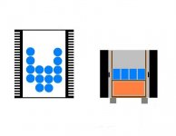
From PSU
Green +24
Yellow -24
Black G
at last, i manage to make it almost zero hum(at least i cant hear anything even i put my ears near to the drivers) with above connections. The picture might too blur to read, but just for simple reference. Thanks andrewT, thanks all. Appreciate yours helps.
Start the signal ground wires from PCB (instead of PSU) and twist them with signal ones.
This will avoid that long run without shielding.
For such lengh, i would prefer shielded (coax) cable.
This will avoid that long run without shielding.
For such lengh, i would prefer shielded (coax) cable.
Looking good, sounds good to hey ! and will only get better.
you will never find a gainclone to soud as good as this,
match it up with some high end yesteryear gear as you can afford it, buy it off ebay, Tannoys etc and you wont want another amp.
Try and get your cables looking tight like this pick.
you will never find a gainclone to soud as good as this,
match it up with some high end yesteryear gear as you can afford it, buy it off ebay, Tannoys etc and you wont want another amp.
Try and get your cables looking tight like this pick.
An externally hosted image should be here but it was not working when we last tested it.
An externally hosted image should be here but it was not working when we last tested it.
From PSU
Green +24
Yellow -24
Black G
at last, i manage to make it almost zero hum(at least i cant hear anything even i put my ears near to the drivers) with above connections. The picture might too blur to read, but just for simple reference. Thanks andrewT, thanks all. Appreciate yours helps.
Do you use fans ? If not, is the temp. of the heasink ok ?
Per post 7880, that non-toroid non-shielded non-star-grounded transformer looks plenty close to be inducing hum in a pot.
I want to switch my f5 with a relay, what should be the minimal output current rating of the relay ?
Does this one ELECTRONIC AND COMPUTER SURPLUS can do the job.
Thanks
Does this one ELECTRONIC AND COMPUTER SURPLUS can do the job.
Thanks
I want to switch my f5 with a relay, what should be the minimal output current rating of the relay ?
Does this one ELECTRONIC AND COMPUTER SURPLUS can do the job.
Thanks
I would find one with double that rating, and then some

To give you a perspective, I use a 16 Ampere (100A surge) mains switch to turn on my F5 at the wall, and every time I flick the switch on, it lights up - literally. You can see the spark jump the gap through the thick white polycarbonate, as a gazillion amperes charge up the 160,000 uF capacitor bank (no inrush protection on mine) . I wouldn't trust anything less than a 30 ampere mains-rated industrial relay with a good surge rating, simply because of the huge inrush current.
I would never use a single relay contact to switch most anything. Multiple contacts for me.
If one uses a big cap bank one would do well to do a step-start consisting of a series resistor (~8-10ohm typically is good) to limit the inrush current, and then something to shunt the resistor for operation. Again I prefer multiple contacts in parallel.
Some people like "globar" thermistors for this function - I'd shunt them out too, if I was going to use such a thing...
Ymmv.
_-_-bear
Getting closer, and ready to order more parts 🙂
Closer ... all i see is dots ................... 😀
Yeah, those things take time 😉 heck, I just felt a need to post something, and this was the best I could think of 😀
"Shame, shame. Shame on you. If you can't dance (draw dotsSo, what parts are you ordering? Blue dots or orange blocks? 😀
 ) too..."

Attachments

As the amp has to "set up" on feet to clear the h/sinks, add the power input socket underneath between the transformers on an angle to get the IEC power cord into it - saves a lot of hassle.
Instead of all those big caps, consider a pair of Cmultipliers, like the F3, as you have room and plenty of spare h/sink area.
Instead of all those big caps, consider a pair of Cmultipliers, like the F3, as you have room and plenty of spare h/sink area.
- Home
- Amplifiers
- Pass Labs
- F5 power amplifier