Massimo,
it looks like a bad solder joint.
It seems you were right, the soldering appeared all good but...
Last time I checked, I got V+ on P-ch mosfet source with pots at zero. Bending lightly the board I got zero or V+ as an intermittent contact was in action.
I've decided to populate a new board (I took a couple for spare and was a good choice at this point) so I desoldered all the components from the "faulty" one. The mosfets seem to work correctly at least with the test alazira mentioned earlier (same procedure can be found at Basic Testing of Semiconductor Devices).
The bare "faulty" board shows a very difficult continuity between both mosfet source and their relative resistor (R11/R12). Could it be the problem?
The other twin mono still works perfectly stable.
Your final words were profetic...............................This is assuming that something else isn't a wrong value or miswired or otherwise malfunctioning...
I'm thinking about building two F5's, a total of four channels, to bi-amp my speakers. How I'd like to biamp them is just tie the two inputs of each amplifier together with a single RCA connector. This would mean that I would only have a single interconnect going to each amp but dual speaker cables going to the bass/treble connectors of my two-way speakers. Referring to the original schematic in post #89 I'm wondering if I'd have to change the values of R9 or R10 to prevent my preamp from seeing half the input impedance it normally would on a power amp. Suggestions anyone?
Regards,
Dan 🙂
Regards,
Dan 🙂
Usually a pre amp out is much lower impedance than the input of a power amp.
My preamp is about 100ohms output impedance and the power amp is 47K input impedance so nothing to worry about there.
My preamp is about 100ohms output impedance and the power amp is 47K input impedance so nothing to worry about there.
I'm thinking about building two F5's, a total of four channels, to bi-amp my speakers...
Dan 🙂
Don't you think a filter between preamp and amps would be a better way?
Fore biamp I would consider a preamp with double preamp modules
The one for woofer amp would have more gain, and additional attenuator
Or just additional preamp module for woofer amp
There are a few with adjustable gain
The one for woofer amp would have more gain, and additional attenuator
Or just additional preamp module for woofer amp
There are a few with adjustable gain
one could tweak the gain at the amp level by adjusting R6 and R7 a bit. probably better to do so on a bass amp side as to not muck up house F5 clone sound.
one could tweak the gain at the amp level by adjusting R6 and R7 a bit. probably better to do so on a bass amp side as to not muck up house F5 clone sound.
If 'Father Pass' and others give my idea a thumbs down then I'll probably go the traditional route with monoblocks.
Regards,
Dan 🙂
Biamping a passive speaker doesnt automatically lead to better sound
I have had no luck with that
Others will say they have
My guess is that it very much depends on the actual speaker, and how its done
But it could be a step on the way to making an active speaker with DSP
But again, I might consider combining F5 with a different kind of amp for the lows
I think a pair of F5 monos would be a good choise fore further devellopments
If you insist on two F5 stereo amps, I would suggest one as pr original F5 with single pair output devices
And the other with double pairs
F5 is 10dB lower gain than a typical power amp - I'd put the attenuator on the woofer side, unless you have 10dB more efficient (sensitive) tweeters... do the math first...
I'd buffer a second output for the woofer, but all buffers do not sound the same... I've yet to find a transparent DSP, but it would be nice...
_-_-
I'd buffer a second output for the woofer, but all buffers do not sound the same... I've yet to find a transparent DSP, but it would be nice...
_-_-
Hi Dant,
you asked about input impedance seen by the source.
Yes the source sees the two power amp inputs in parallel. This should not be a problem with normal cable types/lengths and normal Zin, Rs.
I aim for ~20:1 Zin:Rs.
If Zin=47k//47k then the maximum Rs~1k1. Most CD players and other sources of decent quality can achieve <1k. The exception tends to be valve equipment. They are often of fairly high output impedance irrespective of quality
You also asked about bi-amping.
Yes, you can split the RCA feed and send dual twin runs to the speakers.
If the gains in the two amps are the same then the speaker terminals will see the same voltages and as a result the balance of frequency response will remain as the speaker manufacturer intended.
BTW,
I am one of those non-believers that has ALWAYs heard an improvement in sound quality from the speaker when it is bi-amped.
I have tried converting a passive speaker to active operation using a DCX as the crossover. The conversion was a complete failure. Both the single amped passive and the bi-amped passive outperformed the active by a large margin. I gave up experimenting after approximately a month.
Last edited:
I'm thinking about building two F5's, a total of four channels, to bi-amp my speakers. How I'd like to biamp them is just tie the two inputs of each amplifier together with a single RCA connector. This would mean that I would only have a single interconnect going to each amp but dual speaker cables going to the bass/treble connectors of my two-way speakers. Referring to the original schematic in post #89 I'm wondering if I'd have to change the values of R9 or R10 to prevent my preamp from seeing half the input impedance it normally would on a power amp. Suggestions anyone?
Regards,
Dan 🙂
The input impedance of the F5 is ~100K resistively, but aren't we contending with pretty high input capacitance from the JFET's? I am using a modded Adcom GFP-565 to drive the F5 -- the Adcom in its original form has a compound amplifier in the line stage with an LT1010 "final", so it can source a pretty good amount of current. You might not be so lucky with other sources, but building a buffer is no big deal.
my F5 is alive again,
after having desoldered all the components from the "faulty" board (to be clear I'm not saying that the board from PD was defective, but that the board assembled manifested a problem) I placed them on a brand new board.
I didn't get V+ on P-ch mosfet anymore but no bias at all on both rail.
Swapped the mosfets with a new IRF couple, same result.
Swapped R11 and R12, circuit at work again.
Reinstalled FQAs (the same installed in the previous board), still working well.
It's three hours since then and all is fine.
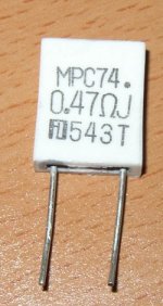
So, it seems the problem was in the two Pana 0.47R 3W. But, were they the cause or the effect?
They appear ok at a first sight, I don't know what's wrong with them. The soldering were good.
after having desoldered all the components from the "faulty" board (to be clear I'm not saying that the board from PD was defective, but that the board assembled manifested a problem) I placed them on a brand new board.
I didn't get V+ on P-ch mosfet anymore but no bias at all on both rail.
Swapped the mosfets with a new IRF couple, same result.
Swapped R11 and R12, circuit at work again.
Reinstalled FQAs (the same installed in the previous board), still working well.
It's three hours since then and all is fine.
So, it seems the problem was in the two Pana 0.47R 3W. But, were they the cause or the effect?
They appear ok at a first sight, I don't know what's wrong with them. The soldering were good.
Attachments
The 0.47R resistors dissipate 0.8W @ idle, but a lot more on peak -- close to 3W -- so make sure they are positioned off the board to allow free air flow.
The 0.47R resistors dissipate 0.8W @ idle, but a lot more on peak -- close to 3W -- so make sure they are positioned off the board to allow free air flow.
Wonderful Jackinnj.
I suspect that this was at least part of my problem(s) with my first attempt at building the F5. Works perfect now. Thanks for supplying the parts in one convenient location. (your website! 😉
Ron
Hi Dant,
you asked about input impedance seen by the source.
Yes the source sees the two power amp inputs in parallel. This should not be a problem with normal cable types/lengths and normal Zin, Rs.
I aim for ~20:1 Zin:Rs.
If Zin=47k//47k then the maximum Rs~1k1. Most CD players and other sources of decent quality can achieve <1k. The exception tends to be valve equipment. They are often of fairly high output impedance irrespective of quality
You also asked about bi-amping.
Yes, you can split the RCA feed and send dual twin runs to the speakers.
If the gains in the two amps are the same then the speaker terminals will see the same voltages and as a result the balance of frequency response will remain as the speaker manufacturer intended.
BTW,
I am one of those non-believers that has ALWAYs heard an improvement in sound quality from the speaker when it is bi-amped.
I have tried converting a passive speaker to active operation using a DCX as the crossover. The conversion was a complete failure. Both the single amped passive and the bi-amped passive outperformed the active by a large margin. I gave up experimenting after approximately a month.
It may change over time but the first thing that's going to feed my F5's is Mr. Pass's B1. Hopefully, the B1 won't get upset when I tie the inputs of two channels of the F5 into a single RCA connector. How does that go? What's sport without risk..............or something like that? 😉
Regards,
Dan 😀
Yet another F5
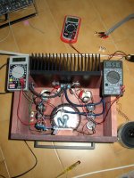
Made a little progress:
-Boards are stuffed (P Daniels)
-CMF 50 and Panasonic resistors
-22,000uF caps
-Antek 3218 300VA 18V toroid
-GBPC3502 vishay bridge rectifiers 200V 60A
-Hifi2000 4U with heatsink case
The psu was tested just before the pic and was putting out 27V unloaded. I suspect that it will be close to 25 when the driver boards are hooked up.
I have really been enjoying my aleph mini but I think the F5 might end up dethroning the little guy.
The 0.47R resistors dissipate 0.8W @ idle, but a lot more on peak -- close to 3W -- so make sure they are positioned off the board to allow free air flow.
Thank you for your suggestion. They were at around 4mm from the board. It should be enough to let air circulate around them.
I changed the two Pana with these Fukushima 5W and at this point I'll change the Pana in the other monoblock as well.
Attachments
- Home
- Amplifiers
- Pass Labs
- F5 power amplifier