I don't know if this has been discussed. Has anyone put combination's of the F3, F4, and F5 in the same chassis using the same power supply and heat sinks. Giving you the ability to switch to different amps. This would give you a choice of what amp would sound best with certain speakers.
Ray
Ray
here's a couple reasons why Lateral MOSFETs don't do so well in this design -- when you get them really cooking into their thermally defensive mode the P and N channels can cool at different rates -- this means that the DC offset will change from the stasis established when set up. The second thing is that to meet the dissipation of the vertical MOSFET's you have to parallel 3 devices so you've really lost any advantage of the lower capacitance of the lateral mosfet. There might be other reasons, but best I can do with respect to THD+N% is about 0.038% @1W 8 ohms which isn't nearly as good as the Fairchild or Vishay (IRF) devices...but primarily, I don't think that they are happy running Class-A.
with respect to THD+N% is about 0.038% @1W 8 ohms which isn't nearly as good as the Fairchild or Vishay (IRF) devices...but primarily, I don't think that they are happy running Class-A.
Yes, but what is the spread of overtones? Mostly second? 😀
There's a 20dB spread between the 2nd and 3rd. Mostly 2nd, a bit of 4th -- not what appears in Chart 9.
Last edited:
There's a 20dB spread between the 2nd and 3rd. Mostly 2nd, a bit of 4th -- not what appears in Chart 9.
Thanks for the reply.
That may explain why I liked the sound of the Old Hitachis when I lashed up a test of them with the F5 input boards. 😉
I've not been able to get the odd harmonics greater than the even ones -- even with IRF devices -- maybe it's something in the water here in NJ.
Electrolysis Aluminum and Copper
How do keep this from happening on suggestion of distributing heat on the Heat Sink?
Ray
How do keep this from happening on suggestion of distributing heat on the Heat Sink?
Ray
You can buy mica in sheets as well as other insulators. If you are using copper for a heatspreader this should not hinder heat dissipation from copper to aluminum much at all.
Uriah
Uriah
With only one pair of outputs why not give each device each its own heatsink
That way theres no need to use any isolators, other that isolate the heatsinks from box/ground, and each other
And heatsink dont need to be that big
Would make nice small monos
But care needed not to touch/short the heatsinks etc
Any safety issues to consider ?
If I should improve heat transfer by using larger isolators, I would consider relatively thick copper no larger than twice the size of device
And use that white heat transfer compound between device and copper
And maybe grind the back of device a bit
If connection isnt 100% tight and smooth, heattransfer may be worse than with "soft" isolators
But adding just another material seem like a winn and loose game, and may be pointless
Are there any proof that it actually works
Setting DC Offset
Hey all,
I fired up my F5. And the output devices do not seem to heat up quickly. So, I turned it off thinking something is a miss. My question is should these output devices heat up right away or is P1 and P2 set to almost zero preventing enough current to flow through the output devices? Not quiet sure. But, P1 and P2 only provide nominal adjustment and my problem is some place else?
Thanks in advance.
Heat Sinks
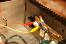
That would require 4 ea. 10" X 6" heat sinks. Two for each mono block, which I think I'll do instead. If I use mica with oxide cream, I don't need to isolate the heat sinks from the cabinet, right. I think 18 gauge wire going from the PC board to the Mosfets should be large enough wire. What do you think.
Ray
With only one pair of outputs why not give each device each its own heatsink
That way theres no need to use any isolators, other that isolate the heatsinks from box/ground, and each other
And heatsink dont need to be that big
Would make nice small monos
But care needed not to touch/short the heatsinks etc
Any safety issues to consider ?
If I should improve heat transfer by using larger isolators, I would consider relatively thick copper no larger than twice the size of device
And use that white heat transfer compound between device and copper
And maybe grind the back of device a bit
If connection isnt 100% tight and smooth, heattransfer may be worse than with "soft" isolators
But adding just another material seem like a winn and loose game, and may be pointless
Are there any proof that it actually works
That would require 4 ea. 10" X 6" heat sinks. Two for each mono block, which I think I'll do instead. If I use mica with oxide cream, I don't need to isolate the heat sinks from the cabinet, right. I think 18 gauge wire going from the PC board to the Mosfets should be large enough wire. What do you think.
Ray
If properly set to zero for initial set-up (verify with meter), then no current will flow. It helps to have two meters when adjusting the pots.Hey all,
I fired up my F5. And the output devices do not seem to heat up quickly. So, I turned it off thinking something is a miss. My question is should these output devices heat up right away or is P1 and P2 set to almost zero preventing enough current to flow through the output devices? Not quiet sure. But, P1 and P2 only provide nominal adjustment and my problem is some place else?
Thanks in advance.
Hey all,
I fired up my F5. And the output devices do not seem to heat up quickly. So, I turned it off thinking something is a miss. My question is should these output devices heat up right away or is P1 and P2 set to almost zero preventing enough current to flow through the output devices? Not quiet sure. But, P1 and P2 only provide nominal adjustment and my problem is some place else?
Thanks in advance.
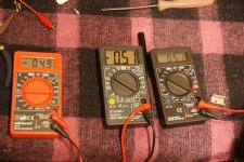
Use a fused power supply when you initially set up the F5 -- and make sure that you have plenty of fuses. I use a pair of Tektronix DM511's which have internal 2A fuses -- and measure the current. They will initially conduct the Idss of the JFETs, as you adjust the potentiometers the current will rise and so will the heat. I do the initial setup with a programmable supply which is limited to 400mA -- when the dc offset is at a minimum and the amp is stable I switch to a power supply which will do a couple hundred watts and gingerly adjust the pots to get 1.3 amps bias and minimal offset. It's best to be patient.
Anyone who wants the assembled lateral MOSFET board to experiment with let me know.
Hi Jackinnj,
Me me me me me me !
I'll pay the S&H.
Thanks.
Audiofanatic 😉
That would require 4 ea. 10" X 6" heat sinks. Two for each mono block, which I think I'll do instead. If I use mica with oxide cream, I don't need to isolate the heat sinks from the cabinet, right. I think 18 gauge wire going from the PC board to the Mosfets should be large enough wire. What do you think.
Ray
Fatter wire please... the gate wire can be thinner.
_-_-bear
Hi.My soundcard is emu1212M.I think it has several hundreds of output impedance.And i think i should use a preamp/buffer(maybeB1 buffer) to drive F5 amp.And there is another way.To buy a AUDIOTRAK Prodigy HD2 soundcard.It has headphone output and good enough to drive F5 amp.Which way is better? Is it a good technic to drive power amplifiers with headphone output of soundcards?(not to use a preamp/buffer and signal cables and I think it can be better for sound quality.because of short signal path and less components.Maybe i am wrong)what do you think?
Last edited:
- Home
- Amplifiers
- Pass Labs
- F5 power amplifier