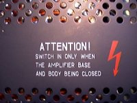
It almost has that KGB look again. 
Trie, dwa, adjin : Boom (тущи свет )
Trie, dwa, adjin : Boom (тущи свет )
Attachments
Last edited:
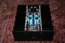
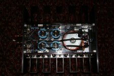
Look like the avionics in Russian fighter jets
yes, it has something like military gears...
style MIG25, rugged high tech.!!
yes, it has something like military gears...
style MIG25, rugged high tech.!!
If I looked into the cockpit of a commercial airliner and saw that, I would run the other way!
I check and there is no short on the input.
Connect the 2 test speakers without any problem on switch on or off.
I think the overhead ceiling fan may contribute to the wandering bias as the bias current varies with the temperature of the heatsink.
Thanks NP for the design and the forum members
kp93300
Connect the 2 test speakers without any problem on switch on or off.
I think the overhead ceiling fan may contribute to the wandering bias as the bias current varies with the temperature of the heatsink.
Thanks NP for the design and the forum members
kp93300
Am I right in reasoning that the bias current varies because of the change in temperature of the Therrnistor ?
kp93300
kp93300
Am I right in reasoning that the bias current varies because of the change in temperature of the Therrnistor ?
kp93300
Yep, for this reason I placed the thermistors (M3 screw-in types) 4cm from the Powerfet in the heatsink. Placing them very close to (or even on) the Fets resulted in some slow thermal drift, and a offset of +/- 10mV. Now my F5 is very, very stable🙂.Succes!
Yep, for this reason I placed the thermistors (M3 screw-in types) 4cm from the Powerfet in the heatsink. Placing them very close to (or even on) the Fets resulted in some slow thermal drift, and a offset of +/- 10mV. Now my F5 is very, very stable🙂.Succes!
So placing the thermsitor 4cm away worked better than placing them closer?
Yes, in my case (each Powerfet has its own heatsink) placing the thermistors directly on the fet's gave some thermal hysteresis (slowly drifting bias per FET). As the N- and P channel fet differ in thermal behaviour you automaticly get the difference in drift as offset on the output. Quit dificult to calculate or simulate, just trie! I used the heatsinks as as some sort of thermal buffer (low deltaT/s). Anyhow, it's worth playing around with the thermistors place and mounting!
Succes.
Succes.
I have read somewhere in this thread that IRFP devices can work without any thermistor...
Just a matter of what works for you and what you think is acceptable in drift/offset. I have some delicate speakers and I like my amps to be stable, no matter what the ambient temp is, and how long they've been on....
In my first setups it did not use any thermistors and each channel settled after something like two hours but. Offset during startup was in the range of +/- 30mV.
I make a silly mistake--please help
Well,
I was enjoying wonderful music with my test speakers .
While trying to adjust the bias and the dc offset, there is some spark and now no sound.
The voltage across R12 near to the IRFP 240 is ZERO. The voltage across R 11 near to IRFP 9240 is 24 V !
DC offset is about .2 to .3 V and cannot be adjusted to zero.
What is the likely problem.?
I think I may have create a short across R12 while testing !
kp93300
I have some delicate speakers
(0.03 x0.03) /16 = 5milliwatts into the speaker.
One of my F5 is dc coupled to my beloved tweeters and i can sleep with that.
Well,
The voltage across R12 near to the IRFP 240 is ZERO. The voltage across R 11 near to IRFP 9240 is 24 V !
DC offset is about .2 to .3 V and cannot be adjusted to zero.
What is the likely problem.?
kp93300
If you have the full +24V over R11 then R11 is probably broken. The fact that you have "only" 0.2V at the output indicates that each Fet , P and N draw no current and might both be broken. Also check both source resistors.
Yes, it is possible to destroy components and keeping the smoke in...
(0.03 x0.03) /16 = 5milliwatts into the speaker.
One of my F5 is dc coupled to my beloved tweeters and i can sleep with that.
Perhaps not a topic to discuss in the F5 forum, but lineairity and distortion of (in your case tweeters) are influenced by offset; giving them a bias that especially has its effect on the lineairity of cone/dome suspension and spiders.
To get an idea the relative importance; just measure the voltage on the tweeter at normal playing level. Just +/-30mV?? 🙂🙂
Hi Snokker,
I checked that R11 is indeed broken measuring about 70 R now.
Do you mean I have to change Q1 to Q4?
Sorry, I have very little electrical knowledge.
Thanks
kp93300
I checked that R11 is indeed broken measuring about 70 R now.
Do you mean I have to change Q1 to Q4?
Sorry, I have very little electrical knowledge.
Thanks
kp93300
Perhaps not a topic to discuss in the F5 forum, but lineairity and distortion of (in your case tweeters) are influenced by offset; giving them a bias that especially has its effect on the lineairity of cone/dome suspension and spiders.
To get an idea the relative importance; just measure the voltage on the tweeter at normal playing level. Just +/-30mV?? 🙂🙂
You are perfectly right. Though i have less than 15mv, i will insert a cap.
- Home
- Amplifiers
- Pass Labs
- F5 power amplifier