I did some simulated tests on the high damping factor version vs standard damping factor version.
I did measurements using a 50Hz square wave into a reactive load.
With standard version I get 10 Volts of over shoot.
With the high damping factor version I get 4 Volts of overshoot.
Mr Pass, in your experience, is this something you would expect to see?
I did measurements using a 50Hz square wave into a reactive load.
With standard version I get 10 Volts of over shoot.
With the high damping factor version I get 4 Volts of overshoot.
Mr Pass, in your experience, is this something you would expect to see?
Last edited:
does F5 sound better with high bias than stock 1.3 A - say 1.6 - 1.9 A
I got conrad MF35 - 151 so I can go high than 1.3 A but what Is reasonable
I am sure that people have tried It - what are your impressions
I got conrad MF35 - 151 so I can go high than 1.3 A but what Is reasonable
I am sure that people have tried It - what are your impressions
Well I haven't listened to mine yet but they definitely measure better.
Nelson reckons simple circuits that measure well, sound swell.
So with that in mind it should sound better.
By how much? that will depend on many things.
If you have very efficient speakers then you won't probably won't hear any improvement at all.
If you have speakers that are less than or equal to 90dB/W/m then you should hear a difference, espescially if they are rated at 4Ohms.
What I would do is keep increasing the bias current until your heat sinks are at about 55 degrees.
i have an F5 that went silent in one channel-but when the power switch is turned off it plays in that channel slightly distorted until the caps bleed down-anyone know what could be causing this???? thanks bubba177
disconnect the speakers and monitor the output offset from both channels before and after switch off.
I did some simulated tests on the high damping factor version vs standard damping factor version.
I did measurements using a 50Hz square wave into a reactive load.
With standard version I get 10 Volts of over shoot.
With the high damping factor version I get 4 Volts of overshoot.
Mr Pass, in your experience, is this something you would expect to see?
Depends heavily on the load.
😎
offset in bad channel 20 volts!!! of course when you shut off offset goes to normal and plays.will try to adjust--but i think somethings hinky
Mica Insulators
I know we discussed Mica insulators way back when. But, I was thinking of ordering some TO-3P Mica insulators from an Ebay seller in Hong Kong (electronics-salon).
He's got a good rating. But, I have been burned before on Ebay from sellers with good ratings.
Have any of you guys have bought from this seller?
As a last resort, I will go with the Keystone Mica insulators. But, they are not a perfect fit and I was trying one last time to find either the correct insulators or larger blank sheets that I can cut to size.
Thanks,
Steve
How about silicon insulators?
http://mouser.com/Thermal-Management/Heatsinks/_/N-5gg0?Keyword=insulators&FS=True
Mica Insulators
Thanks cviller,
I've tried those before. I wanted to go with Mica this time. Last time I had to remove the Mosfets from the heatsink in order to work on the board, and I wasn't crazy about reusing the pads. I used them again. But I think with Mica and goop, I can go on and off multiple times without concern.
Thanks again,
Steve
I use mica an goop too, but they seem harder to find here in the US than back home. It just sounds silly to order them from hong kong though... 😉
Mica
I can't argue with that. I would much rather purchase from the US. Plus I'm not a big fan of Ebay after a few not so nice experiences.
Steve
I can't argue with that. I would much rather purchase from the US. Plus I'm not a big fan of Ebay after a few not so nice experiences.
Steve
hi everyone!
ı have tried to do f5 abaout one year.
ı'll finish the case of amplifier very soon,ı think ı'll finished whole work 4-5 month ago and ı made a pcb for f5.
on the pcb the termal control device is taken out because ı want it to be flat.
my orginal aim is getting some ide for f5 and pcb
ı have tried to do f5 abaout one year.
ı'll finish the case of amplifier very soon,ı think ı'll finished whole work 4-5 month ago and ı made a pcb for f5.
on the pcb the termal control device is taken out because ı want it to be flat.
my orginal aim is getting some ide for f5 and pcb
An externally hosted image should be here but it was not working when we last tested it.
I recently bought a bunch of mica TO-3P insulators from MCM to replace some flaky old ones in an onkyo I was repairing. They seem to be fine. I think they were a pack of 25 for $5.00.
Yeah, its neat
I have been working on a double output version, but not finished yet
Leaving out Q5/Q6 would surely make it simpler
Whats the effect of leaving out Q5/Q6, pros and cons (I know its been covered before)
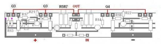
Looks like it would be very easy to make the board half as wide by moving R11/R12 closer to heatsink, and maybe turn R5/6/7/8 90gr
Is it ok to have supply connections so close to input Q1/Q2 ?
I have been working on a double output version, but not finished yet
Leaving out Q5/Q6 would surely make it simpler
Whats the effect of leaving out Q5/Q6, pros and cons (I know its been covered before)
Looks like it would be very easy to make the board half as wide by moving R11/R12 closer to heatsink, and maybe turn R5/6/7/8 90gr
Is it ok to have supply connections so close to input Q1/Q2 ?
Attachments
Last edited:
F5 sound sweet but short on bass...help...
Hi
I have completed an F5 and I am impressed on the sound for a 4 transistors only amp (if we exclude the current protection bjts). However, the bass is definitely less deep and strong than all my other DIY amps. Here are some implementations details:
-Power supply (mono configuration to supply both channels):
2 x 300 VA in series (each 9Vac) to get +/- 24 Vdc
2 x 35 amps bridges
2x C-R-C config caps: 36000uf - 0.167 ohms - 36000uf (thus 144000uf total)
(the 4 x 36000uf are bypassed with 220nf MKT caps)
- AMP:
Standard F5 design with a single pair of IRFP240/9240
Bias current of about 1.3 A per channel
Input cap of 10uf MKP series
-Speakers:
Monitor audio RS-8
93db, 6 ohms
I post here so some of you can guide me to identify if this is the usual F5 sound signature or something is wrong or can be improved in my implementation.
Thanks
Last edited:
- Home
- Amplifiers
- Pass Labs
- F5 power amplifier