Cant wait to see your results and we all appreciate pictures. It will be interesting to see how much heat you can remove that way.
Uriah
Uriah
Big DC offset at cold amp power-up...
Hi,
😕
I just built one F5 channel. I have adjusted the DC offset after a few hours at heatsinks temperature of about 52 deg C (close to the mosfet) to about +50mv (with about 1.2 amp bias). When I power cycle the amp while it has not reach room temperature, the DC offset is no more than +/-100mv at start-up and then reach the +50mv after a short while. However, upon a power up at room temperature I get about -700mv and then it slowly stabilizes to +50mv after about half an hour or so. This is the first time I experience such a thing on my DIY power amp. Is it normal? What do you get as a DC offset voltage upon cold power up?
I have matched the input jfet to about 1% VGS with 10 ohm source resistors.
Each mosfet has its own same model heatsink with same orientation and are tied together with an aluminum plate. I have also mounted the thermistors on the aluminum plate.
Thanks
Fab
Hi,
Most probably this is a problem of the input jfets and the dependany they have from the temp.As the jfets are heated due to current flowing from them the currnt changes and you have DC variations. In most of the cases this is because one or both of the complementary jfets are working close to their current limit. I had the same problem with another amp, and different jfets than k170 and j74. The solution for me was to bring the complementary in proximity so they had the same temperature. Also I replased them with jfets with grater current capabilities (bigger Idss). bigger Idss gives smaller temperature dependened variations. Also I do not think that you have to have the thermistors directly mounted to the heatsing because then you are sensing faster temperatures changes. Try that first, have the thermistor in small proximity of the mosfets (~0.5-1 cm) and adjust again. If this does not succed consider the previous.
I hope the above to help you.
DC offset at colf power up
Thanks for the suggestions. I had forgot to mention that my input jfets are already tied together with heatshrink around them. The jfets have measured IDss of about more than 10V and the 10 ohms source resistor imposes the ID relative value accordingly.
I will give a try with the thermistors location change and maybe change the value of resistor in series with the thermistor.😕
What do YOU have for COLD power up DC offset and also warm power up?
Thanks
Hi,
Most probably this is a problem of the input jfets and the dependany they have from the temp.As the jfets are heated due to current flowing from them the currnt changes and you have DC variations. In most of the cases this is because one or both of the complementary jfets are working close to their current limit. I had the same problem with another amp, and different jfets than k170 and j74. The solution for me was to bring the complementary in proximity so they had the same temperature. Also I replased them with jfets with grater current capabilities (bigger Idss). bigger Idss gives smaller temperature dependened variations. Also I do not think that you have to have the thermistors directly mounted to the heatsing because then you are sensing faster temperatures changes. Try that first, have the thermistor in small proximity of the mosfets (~0.5-1 cm) and adjust again. If this does not succed consider the previous.
I hope the above to help you.
Thanks for the suggestions. I had forgot to mention that my input jfets are already tied together with heatshrink around them. The jfets have measured IDss of about more than 10V and the 10 ohms source resistor imposes the ID relative value accordingly.
I will give a try with the thermistors location change and maybe change the value of resistor in series with the thermistor.😕
What do YOU have for COLD power up DC offset and also warm power up?
Thanks

What do YOU have for COLD power up DC offset and also warm power up?
Thanks
Just thought I'd post my cold turn on offsets.
They are 70mv and 50mv, they drop quickly
and after 30 seconds are 12mv and 30mv.
After ten minutes they are 2mv and -2mv.
For got to take measurements before turn off
after two hours. But, if I remember correctly
they had remained the same at turn off.
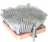
I just did some calculations.
One of these heatsinks will dissipate 200W for a 30 degree (celsius) rise above ambient with the right type of fan (ie very noisy). OK for testing.
For a silent setup (ie quiet fan) it will dissipate 130W.
One of these heatsinks will dissipate 200W for a 30 degree (celsius) rise above ambient with the right type of fan (ie very noisy). OK for testing.
For a silent setup (ie quiet fan) it will dissipate 130W.
I just did some calculations.
One of these heatsinks will dissipate 200W for a 30 degree (celsius) rise above ambient with the right type of fan (ie very noisy). OK for testing.
For a silent setup (ie quiet fan) it will dissipate 130W.
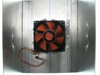
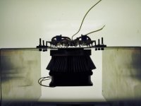
very interesting if this works out good for you. 130w is a good achievement, what's one of those things cost? Is it cheapert than a appropriate heatsink?
I am a bit of a computer geek. So I had it laying around not being used.
I think I might have paid $40 for it but I can't be sure.
I think I might have paid $40 for it but I can't be sure.
I think Peter Daniel did something similiar to the CPU heatsink as a test with an F5, but it ran too hot. I don't think the Fan was used however.
🙁I've got a question about R21/R22.
Mr PASS says that the value could be from 10K to 22K.
Is there something to modify if using 15K ?
What is affected by those resistors values ?
I'm using FQA12P20 and FQA19N20C MosFets, provided by EUVL (thanks to him).
Thanks for your help
P.7 & 8 of the original publication in PDF detailed the function (protection) and method to calculate the values of those resistors, including R21,22.
Pls read and try to understand the article first. It was written for good purposes.
Patrick
Pls read and try to understand the article first. It was written for good purposes.
Patrick
Patrick, I'm not as familiar with those concepts as you are...😉
BTW reading pages 7/8 don't give me the expected answer by now.
I've read in the OM page 11, some interesting tip about R21/22 :
"Since the 1.3 amps bias through the .47 ohm Source resistors provides at 0.6 volts already, we have to divide that voltage down so that limiting occurs at a higher current. We do this for Q5 with divider resistors R17 and R19, and for Q6 with R18 and R20. R21 and R22 allow us to also adjust the limit point based on some information from the output voltage."
You're right I've got to undertand the purpose of those R.
I've checked F5 thread this morning about values required while using IR MosFets.
Nothing special mentionned in unbalanced configuration.
Thanks
Attachments

Last edited:
They measure better with 10K, but sound better with 22K
or higher.
Thank you for the enlightment Mr PASS

DC offset at cold turn on
Thanks for the info. I have decided to mount the second channel to see if it behaves different ...and it does. Offset is no more than 70mv at cold power up (more than 7 hours off) and then reduces quickly.
Then, I remembered that I blew up one 0.47 ohms mosfet source resistor during test of the first channel. Thus, I have decided to change also the other 0.47 ohms source resistor ( I now use 0.5 ohms Vishay/Dale Silicone Wirewound for both source resistors since this is what I had stock...). I will leave the amp off for the night and check the difference tomorrow.
Just thought I'd post my cold turn on offsets.
They are 70mv and 50mv, they drop quickly
and after 30 seconds are 12mv and 30mv.
After ten minutes they are 2mv and -2mv.
For got to take measurements before turn off
after two hours. But, if I remember correctly
they had remained the same at turn off.
Thanks for the info. I have decided to mount the second channel to see if it behaves different ...and it does. Offset is no more than 70mv at cold power up (more than 7 hours off) and then reduces quickly.
Then, I remembered that I blew up one 0.47 ohms mosfet source resistor during test of the first channel. Thus, I have decided to change also the other 0.47 ohms source resistor ( I now use 0.5 ohms Vishay/Dale Silicone Wirewound for both source resistors since this is what I had stock...). I will leave the amp off for the night and check the difference tomorrow.
Last edited:
Yarq
Yet another regulation question:
I would be less apologetic if I could find specific information using the search function both within threads and across forums. It is like going down rabbit holes.
I need to regulate my 24v toroid which becomes 36v back down to 24v after the bridge rectifier. Most options I find are either too noisy for the F5 or can't manage the current demands. I have looked for hours and am having little luck. I know there are many ways to do this in general but I am specifically wanting to put something in place after the bridge and before the C1-C8 in the PSU.
Thanking all in advance.
Bruce
- Home
- Amplifiers
- Pass Labs
- F5 power amplifier